


1083286-UIM-L-1219
Johnson Controls Ducted Systems
7
RESIDENTIAL AND MODULAR HOME UPFLOW
RETURN PLENUM CONNECTION
Return air may enter the furnace through the side(s) or bottom depend-
ing on the type of application. Return air may not be connected into the
rear panel of the unit.
SIDE RETURN APPLICATION
Side return applications pull return air through an opening cut in the
side of the furnace casing. This furnace is supplied with a bottom block-
off panel that should be left in place if a side return is to be used. If the
furnace is to be installed on a flat, solid surface, this bottom panel will
provide an adequate seal to prevent air leakage through the unused
bottom opening. However, if the furnace is to be installed on a surface
that is uneven, or if it is to be installed on blocks or otherwise raised off
the floor,
it will be necessary to seal the edges of the bottom panel
to the casing using tape or other appropriate gasket material to
prevent air leakage.
BOTTOM RETURN AND ATTIC INSTALLATIONS
Bottom return applications normally pull return air through a base plat-
form or return air plenum. Be sure the return platform structure or return
air plenum is suitable to support the weight of the furnace.
The internal bottom panel must be removed for this application.
Attic installations must meet all minimum clearances to combustibles
and have floor support with required service accessibility.
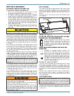
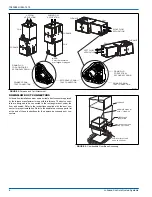
HORIZONTAL APPLICATION
ATTIC INSTALLATION
This appliance is certified for line contact when the furnace is installed
in the horizontal left or right position. The line contact is only permissible
between lines that are formed by the intersection of the top and two
sides of the furnace and the building joists, studs or framing. This line
may be in contact with combustible material. Refer to Figure 5.
When moving or handling this furnace prior to installation it is recom-
mended to leave the doors on the furnace to provide support and to
prevent damage or warping of the cabinet. When lifting the furnace,
support the ends of the furnace rather than lifting by the cabinet flanges
at the return air openings (bottom or sides) or supply air opening.
It is acceptable to use the primary heat exchanger tubes as a lifting
point provided that the tubes are lifted at the front of the heat exchang-
ers where attached to the vestibule panel. Do not use the top return
bend of the heat exchangers as lifting points as the tubes may shift out
of position or their location brackets/baffles.
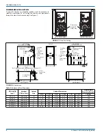
SUSPENDED FURNACE / CRAWL SPACE
INSTALLATION
The furnace can be hung from floor joists or installed on suitable blocks
or pads. Blocks or pad installations shall provide adequate height to
ensure that the unit will not be subject to water damage.
Units may also be suspended from rafters or floor joists using rods, pipe
angle supports or straps. In all cases, the furnace should be supported
with rods, straps, or angle supports at three locations to properly sup-
port the furnace. Place one support at the supply end of the furnace,
one support located approximately in the center of the furnace near the
blower shelf, and the third support should be at the return end of the fur-
nace. Maintain a 6” (15.2 cm) minimum clearance between the front of
the furnace and the support rods or straps.
All six suspension points must be level to ensure proper and quiet fur-
nace operation. When suspending the furnace, use a secure platform
constructed of plywood or other building materials secured to the floor
or ceiling joists. Refer to Figure 6 for details and additional information.
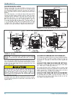
FIGURE 4:
Horizontal Application
IMPORTANT:
This furnace may be installed in a horizontal position
on either side as shown above.
It must not be installed on its back.
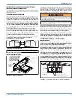
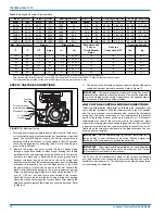
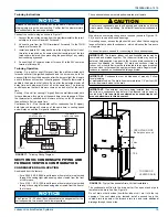
FIGURE 5:
Typical Attic Installation
Return
Air
Sediment
Trap
Gas Piping
Supply
Air
Vent (Maintain
required
clearances to
combustibles)
Line contact only permissible
between lines formed by the
intersection of furnace top
and two sides and building
joists, studs or framing
30” MIN.
Work Area
Filter rack
must be a minimum
distance
of 18” (45.7 cm)
from the
furnace
WARNING
When a furnace is installed in an attic or other insulated space, keep
all insulating materials at least 12” (30.5 cm) away from furnace and
burner combustion air openings.
IMPORTANT: During installation, doors should remain on the
furnace when moving or lifting.
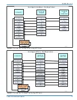
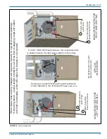
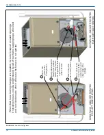
FIGURE 6:
Typical Suspended Furnace / Crawl Space Installation
!
Support
Rod
Support
Angle (x3)
Maintain 6” minimum
clearance between support
rods and front of furnace


