


505309-UIM-D-0511
Johnson Controls Unitary Products
33
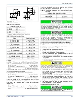
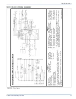
NOTES:
1.Airflow expressed in standard cubic feet per minute (CFM).
2.Return air is through side opposite motor (left side).
3.Motor voltage at 115 V.
4.Airflow through across motor side (right side) may be slightly less than the data shown above.
Blower Performance CFM - Any Position (without filter)
Bottom Airflow Data (SCFM)
Models
Speed
Ext. Static Pressure (in. H2O)
0.1
0.2
0.3
0.4
0.5
0.6
0.7
0.8
0.9
1.0
060B12MP11
High
1492 1442 1378 1325 1243 1176 1075 966 849 655
Medium
High 1236 1201 1161 1139 1082 1011 919 830 715 590
Medium
Low 986 950 961 916 872 831 757 703 600 510
Low
824 795 783 744 713 659 624 554 489 389
080B12MP11
High
1597 1537 1484 1435 1370 1286 1230 1155 1075 925
Medium
High 1338 1307 1273 1223 1179 1123 1065 998 928 812
Medium
Low 1113
1094
1077
1043
1008 972 924 868 803 798
Low
937 916 900 877 854 817 775 718 639 560
080C16MP11
High
1919 1865 1802 1738 1671 1600 1517 1414 1322 1201
Medium
High 1532 1533 1513 1499 1465 1416 1352 1283 1198 1084
Medium
Low
1232 1313 1291 1280 1250 1209 1207 1148 1055 937
Low
826 821 853 858 838 817 794 776 760 711
100C16MP11
High
1909 1880 1823 1776 1706 1637 1562 1474 1375 1252
Medium
High 1465 1463 1469 1485 1477 1416 1386 1324 1250 1114
Medium
1190 1222 1216 1215 1224 1189 1158 1145 1087 996
Low
787 834 819 836 819 810 790 761 690 707
100C20MP11
High
2284 2205 2114 2021 1934 1848 1752 1653 1505 1397
Medium
High 1967 1905 1824 1763 1712 1628 1551 1473 1379 1213
Medium
Low
1610 1563 1513 1480 1430 1367 1319 1261 1101 1012
Low
1326 1304 1267 1232 1183 1143 1080 1003 871 798
120D20MP11
High
2341 2245 2153 2072 1977 1876 1769 1642 1506 1306
Medium
High 2002 1952 1878 1823 1739 1657 1563 1458 1322 1185
Medium
Low
1615 1579 1533 1473 1430 1368 1282 1186 1091 953
Low
1352 1295 1259 1245 1190 1141 1076 998 938 820
Left Side Airflow Data (SCFM)
Models
Speed
Ext. Static Pressure (in. H2O)
0.1
0.2
0.3
0.4
0.5
0.6
0.7
0.8
0.9
1.0
060B12MP11
High
1470 1406 1361 1309 1241 1155 1060 920 775 628
Medium
High 1211
1186
1139
1101
1042 980 896 796 681 545
Medium
Low 970 957 927 889 853 796 745 660 568 450
Low
793 781 756 724 694 653 585 530 469 382
080B12MP11
High
1605 1562 1514 1454 1393 1330 1251 1169 1073 940
Medium
High 1372 1318 1280 1255 1205 1161 1093 1023 943 849
Medium
Low 1087
1073
1052
1003 993 953 897 843 775 709
Low
916 896 881 854 831 802 757 708 642 574
080C16MP11
High
1956 1907 1846 1778 1717 1647 1573 1483 1353 1209
Medium
High 1543 1543 1516 1504 1477 1446 1382 1309 1202 1099
Medium
Low
1238 1241 1243 1241 1252 1242 1201 1140 1074 967
Low
906 902 903 910 888 866 859 829 795 743
100C16MP11
High
1828 1829 1789 1768 1727 1671 1601 1505 1390 1272
Medium
High 1422 1444 1437 1424 1396 1326 1301 1253 1200 1100
Medium
1224 1229 1243 1234 1219 1193 1168 1135 1088 977
Low
813 819 818 814 783 762 756 732 690 642
100C20MP11
High
2391 2286 2165 2079 2004 1934 1839 1692 1560 1366
Medium
High 1945 1878 1838 1782 1694 1642 1565 1451 1334 1163
Medium
Low
1549 1530 1495 1430 1431 1365 1284 1192 1097 1022
Low
1256 1229 1189 1159 1089 1033 1008 950 871 784
120D20MP11
High
2343 2253 2167 2071 1979 1881 1785 1668 1473 1351
Medium
High 1954 1892 1846 1781 1714 1637 1548 1429 1238 1171
Medium
Low
1596 1539 1511 1458 1399 1341 1254 1180 942 988
Low
1299
1261
1229
1177 1111 1053 993 937 882 782


