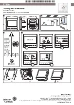


T7600
P/N 24-85784-00151 Rev. D Issue Date: 07 2019
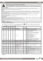
INSTALLATION INSTRUCTIONS FOR THE TECHNICIAN / FITTER
READ THIS INSTRUCTION SHEET AND THE SAFETY WARNINGS CAREFULLY BEFORE INSTALLING AND
SAVE IT FOR FUTURE USE
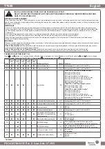
REPAIR AND REPLACEMENT
Do not attempt to repair the T7 Series thermostat. In case of an improperly functioning control, contact the nearest Johnson Controls
®
representative, and
specify the desired product code number. When contacting the supplier for a replacement please state the type/model number of the control located on the
data plate or cover label.
IMPORTANT
• Use this T7 Series
Thermostat only as an operating control. Where failure of malfunction of the T7 Series Thermostat could lead to personal injury or
property damage to the controlled equipment or other property, additional precautions must be designed into the system. Incorporate and maintain other
devices such as supervisory or alarm systems or safety or limit controls intended to warn of, or protect against, failure or malfunction of the T7 Series
Thermostat.
•
Do not install this thermostat in condensing, wet, or damp environments. Moisture may cause damage to the thermostat.
•
Do not remove PCB from the enclosure cover. Removing the PCB from the enclosure cover voids the product warranty.
•
Make all wiring connections in accordance with local, nation, and regional regulations. Do not exceed the T7 Series thermostat’s electrical ratings.
• Remove LCD plastic cover before use.
WARNING
Disconnect power supply before making electrical connections. Contact with components carrying hazardous voltages can cause electrical shock and may
result in severe personal injury or death.
•
Risk of Electrical Shock:
Ground the thermostat according to local, national, and regional regulations. Failure to ground the thermostat may result in
electrical shock and severe personal injury and death.
•
Risk of Electrical Shock and Property Damage:
Insulate and secure each unused wire lead before applying power to the thermostat.
Failure to insulate and secure each unused wire lead may result property damage, electrical shock, and severe personal injury or death.
English
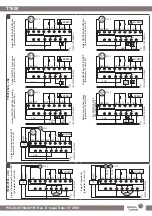
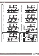
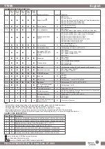
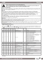
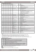
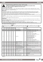
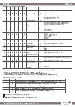
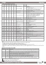
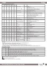
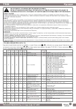
PARAMETER SETTING (PART 1/2)
Press
and
button for 5 seconds at power off mode to get in parameter list. Press
M
button to scroll the list and use
and
button to change
parameter value. With model T7603-T000-...JF0 only press
to get parameter list and
to scroll the list.
Code
T7600-
TF21-
...JS0
T7601-
TF20-
...JS0
T7600-
TF20-
...JS0
T7603-
T000-
...JF0
T7600-
TB21-
...JA0 Parameter Name
Default Function
01
■
■
■
■
■
Lower setpoint limit
5°C
Setting range 0°C to 38°C (32°F to 95°F)
02
■
■
■
■
■
Upper setpoint limit
35°C
Setting range 2°C to 40°C (36°F to 99°F)
03
■
■
■
---
---
Application
00
T7601-TF20-...JS0 with EC Motor Control
00:
2-pipe ON/OFF valve
01:
4-pipe ON/OFF Valve
02:
2-pipe ON/OFF 3-wire relay valve
03:
2-pipe ON/OFF valve with TiO2/ESP relay
04:
2-pipe ON/OFF valve with floor heating
05:
Water source heat pump
06:
2-pipe Proportional valve
T7600-TF21-...JS0 Proportional Control
00:
2-pipe Proportional valve
01:
4-pipe Proportional valve
T7600-TF20-...JS0 ON/OFF Control
00:
2-pipe ON/OFF valve
01:
4-pipe ON/OFF Valve
02:
2-pipe ON/OFF 3-wire relay valve
03:
2-pipe ON/OFF valve with TiO2/ESP relay
04:
2-pipe ON/OFF valve with floor heating
05:
Water source heat pump
04
■
■
■
---
■
Cooling setpoint unoccupied
26°C
Setting range 22°C to 32°C (72°F to 90°F)
05
■
■
■
■
■
Heating setpoint unoccupied
18°C
Setting range 10°C to 21°C (50°F to 70°F)
06
■
■
■
■
■
Frost protection
00
00:
On
01:
Off
07
■
■
■
■
■
Frost protection setpoint
5°C
Setting range 0°C to 20°C (32°F to 68°F)
08
■
■
■
---
■
Fan speed in AUTO mode in
dead band (room temperature
reach set point)
01
00: Fan off
01: Low speed
09
■
■
■
---
■
Fan mode when unoccupied
00
00:
Low speed
01:
Set speeds
10
---
■
---
---
---
ECM Min voltage
3V
Min voltage below which the fan output is 0%,
range 0 V-10 V. The adjustment is 0.5V for every step..
11
---
■
---
---
---
ECM Max voltage
10V
Max voltage above which the fan output is 100%,
range 0 V-10 V. The adjustment is 0.5V for every step
12
---
■
---
---
---
ECM cut off relay (F-ON)
00
00:
Disabled
01:
Enabled
13
■
■
■
■
■
Restart after power failure
00
00:
Keep last status
01:
On
02:
Off
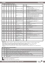
...Continued...