1010352-UUM-N-0121
4
Johnson Controls Ducted Systems
Operating instructions
1.
Stop
. Read the safety information above for your protection.
2. Set the thermostat to the lowest setting in the heat mode.
3. Turn off all electric power to the appliance.
4. Remove the furnace burner access panel/door.
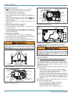
5. Move (do not force) the gas control switch to the
off
position. See
Figures 7 to 9.
6. Wait 5 min to clear out any gas. If you then smell gas,
stop
. Follow
Step 2 in the
Safety
information on page 1. If you do not smell gas,
go to the next step.
7. Move (do not force) the gas control switch to the
on
position. See
Figures 7 to 9.
8. Replace the furnace burner access panel/door.
9. Turn on all electric power to the appliance.
10. Set the thermostat to the preferred setting. The burner may take
30 s to 60 s to ignite.
11. After three trials for ignition, if the appliance does not operate, fol-
low the instructions
Turning off the appliance
and call your service
technician or gas supplier.
Turning off the appliance
1. Set the thermostat to the lowest setting in the heating mode.
2. Turn off all electric power to the appliance if servicing the appliance.
3. Remove the furnace burner access panel/door.
4. Move the gas control switch to the
off
position. See Figures 7 to 9.
5. Replace the furnace burner access panel/door.
SECTION IV: FURNACE MAINTENANCE - USER
INFORMATION
External air filters
Filters used with this furnace must be installed external to the furnace
casing.
Do not
attempt to install filters inside the furnace cabinet.
Some installations may have the air filter in a rack attached to the cas-
ing of the furnace or placed in the return air duct. If the filter location or
replacement process is not obvious, contact your installer or service
technician for assistance.
Every time the external air filters are changed, the following items must
be visually inspected:
• Check combustion air and vent pipe for blockage or leakage.
• Check all components to ensure they are in good condition and
that there are no obvious signs of deterioration.
• Check the drain lines to make sure there are no cracks or leaks.
• Check for dirt or lint on any surfaces or on components. Do not try
to clean any of the surfaces or components. Cleaning of the fur-
nace and its components must be done by a qualified service pro-
fessional.
Do not
operate the furnace if, during the inspection of your furnace, you
find any of the following conditions:
• Excessive amounts of dust and lint on components
• Damaged or deteriorated components or surfaces
• Leaks or blockage in the vent pipe passages
• Water on any surface inside or outside of the furnace
WARNING
Should overheating occur, or the gas valve fail to shut off, turn the
external manual gas valve in the gas supply line to the furnace to the
off position and let the furnace cool off before shutting off the electri-
cal power supply.
Figure 8:
Gas Piping
Figure 9:
Single Stage Gas Valve
!
([WHUQDO0DQXDO
6KXWRII9DOYH
7R*DV
6XSSO\
7R*DV
6XSSO\
*URXQGHG-RLQW8QLRQ
PD\EH,QVWDOOHG
,QVLGHRU2XWVLGH8QLW
'ULS/HJ
$
INLET
WRENCH
BOSS
INLET
PRESSURE
PORT
ON
OFF
ON/OFF SWITCH
(Shown in ON position)
MAIN REGULATOR
ADJUSTMENT
OUTLET
OUTLET
PRESSURE
PORT
VENT PORT
A0226-001
Figure 10:
Two-Stage Gas Valve
Figure 11:
Modulating Gas Valve
WARNING
Before proceeding, be sure the area is well ventilated. Turn the ther-
mostat off. If the blower is running, wait until it stops automatically.
Turn off the gas and electrical power supplies to the furnace. Check
all metal parts and surfaces to be sure they have cooled to room tem-
perature before you begin.
287/(7
35(6685(
3257
+,*+67$*(5(*8/$725
$'-8670(17
9(17
3257
287/(7
/2:67$*(5(*8/$725
$'-8670(17
212))
6:,7&+
,1/(7
35(6685(
3257
:5(1&+
%266
,1/(7
$
,QOHW
3UHVVXUH
7DS
2XWOHW
3UHVVXUH
7DS
2Q2II
6ZLWFK
0DLQ
5HJXODWRU
$GMXVWPHQW
$
!


