


8 Conventional Products—2400 and 2400TH Direct 2-Wire Smoke Detectors
NFPA-72-National Fire Alarm Code defines the spacing requirements for
smoke detectors. Typically, this is 30 feet when the detectors are
installed on a smooth ceiling. However, all installations must comply
NFPA-72-National Fire Alarm Code and/or special requirements of the
authority having jurisdiction.
All wiring must be installed in compliance with the National Electrical
Code, all applicable local codes, and any special requirements of the local
authority having jurisdiction. Proper wire gauges should be used. The
conductors used to connect smoke detectors to control panels and
accessory devices should be color-coded to reduce the likelihood of wiring
errors. Improper connections can prevent a system from responding
properly in the event of a fire.
For Initiating Device Circuit (IDC) wiring (the wiring between
interconnected detectors as well as the control panel), it is recommended
that the wire be no smaller than No. 18 American Wire Gauge (AWG)
(1.0 square mm). However, the screws and clamping plate in the base can
accommodate wire sizes up to No. 12 AWG (3.3 square mm). The use of
twisted pair wiring for the detection/power (+ and -) wires is
recommended to minimize the effects of electrical interference.
Smoke detectors and alarm system control panels have specifications for
allowable IDC resistance. Consult the control panel manufacturer’s
specifications for the total IDC resistance allowed for the control panel
being used before wiring the detector IDCs.
To make wire connections:
1.
Strip about 3/8 inch of insulation from the end of the wire.
2.
Slide the bare end of the wire under the clamping plate.
3.
Tighten the clamping plate screw.
Please note carefully the wiring diagram for a typical 2-wire detector
system shown in Figure 3.
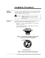
Spacing
Wiring
Installation
Guidelines