Subject to change without notice. Published in U.S.A.
835961-UIM-A-0112
Copyright
©
2012 by Johnson Controls, Inc. All rights reserved.
Supersedes: 550377-UIM-D-1211
Johnson Controls Unitary Products
5005 York Drive
Norman, OK 73069
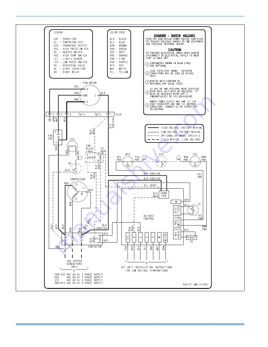
FIGURE 17:
Wiring Diagram - Three Phase (Time-Temp)


