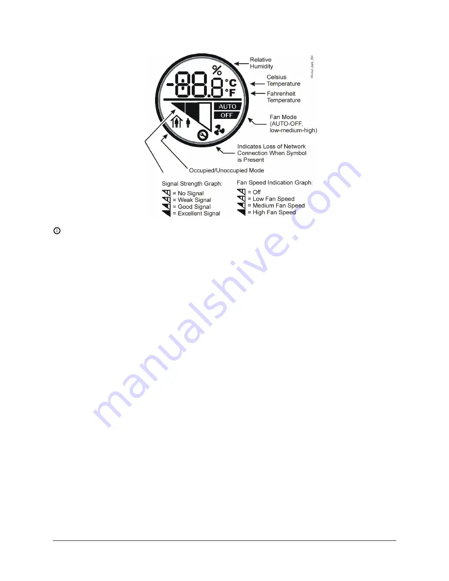
Figure 7: Sensor LCD(FX-WRZTHJ, FX-WRZTTJ, FX-WRZTTK Models)
Note:
For FX-WRZ Series Sensors with an LCD display, the humidity value may appear as 0.0%
when the sensor is joining a network. This condition is transitory and does not transfer to the
Building Automation System (BAS).
An optional FX-WRZSST-120 Wireless Sensing System Tool can also be used with any FX-WRZ Series
Sensor prior to installation as a site survey tool to determine potential locations for system devices
and the wireless signal strength between the system devices in the application.
Refer to the
FX-WRZSST-120 Wireless Sensing System Tool Installation Instructions (Part No. 24-10563-71)
for more information on testing signal strength. For additional location consideration details, also
refer to the following documents:
•
FX-ZFR Series Wireless Field Bus System Technical Bulletin (LIT-12011660)
•
FX-WRZ7860 One-to-One Wireless Sensing System Technical Bulletin (LIT-12011663)
Temperature setpoint adjustment
You can use the temperature setpoint adjustment buttons on the face of the network sensor to
adjust the temperature setpoint. Press the up arrow button to increase the setpoint or the down
arrow to decrease it. The new setpoint stops flashing and becomes fixed after a few seconds.
°C/°F temperature mode selection
All models include a °C/°F pushbutton on the face of the network sensor to provide temperature
scale options for display. Pressing the pushbutton toggles the temperature mode between
Fahrenheit and Celsius on the LCD.
Rapid transmit mode
Rapid Transmit Mode forces wireless transmissions between the sensor and the parent FX-ZFR18xx
Series Router or FX-WRZ7860 Receiver, and indicates wireless signal strength between the devices.
To force the FX-WRZ Series Sensor into rapid transmit mode:
9
Temperature and Relative Humidity FX-WRZ Series Wireless Room Sensors Installation Instructions


