IDC INDUCED DRAFT EVAPORATIVE CONDENSERS
INSTALLATION
S140-500 IOM (FEB 08)
Page 7
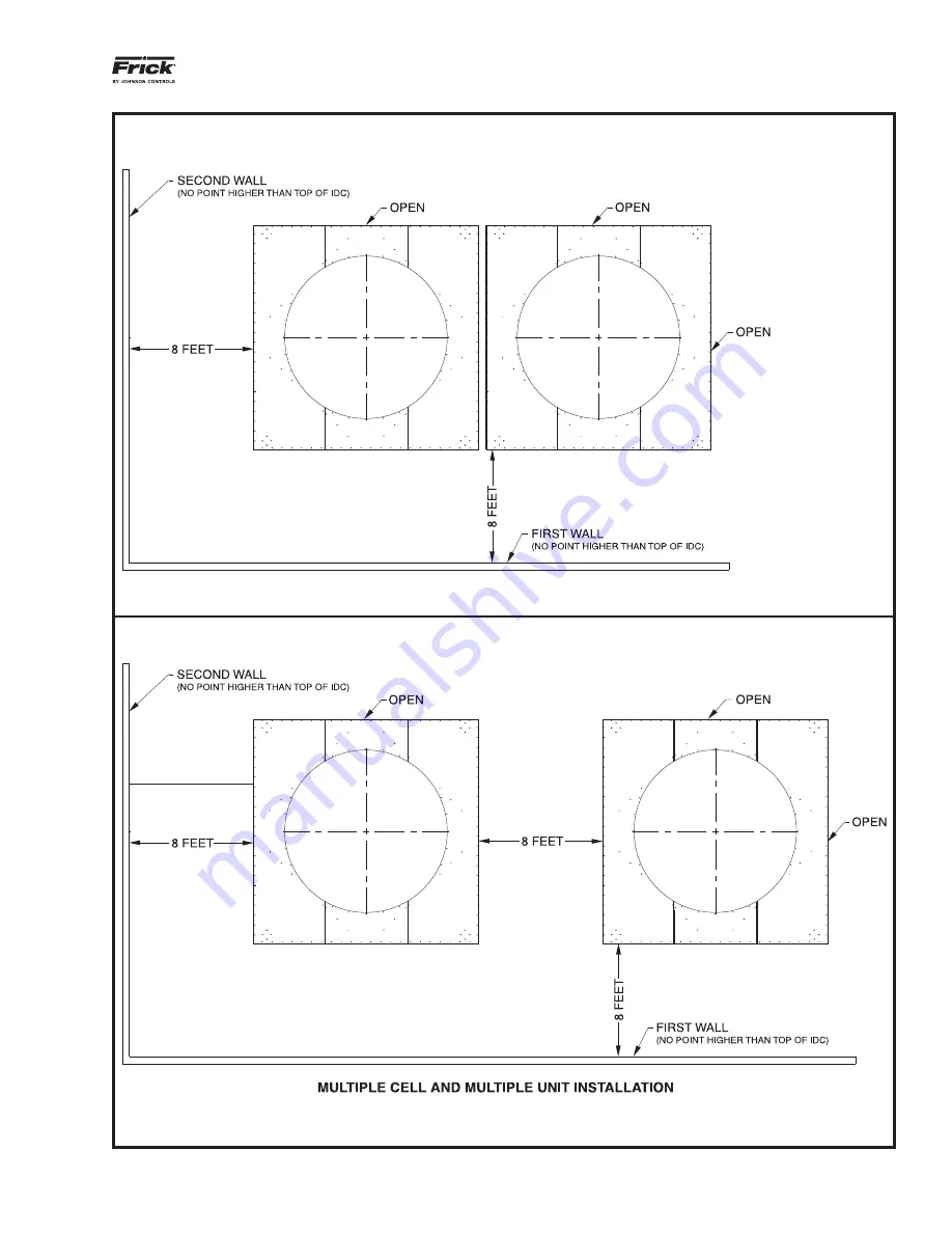
Figure 1-3. IDC Unit-to-Wall Spacing Requirements (Multiple Cell and Multiple Unit Installation)
Page 1: ...om for the latest version of this publication IDC INDUCED DRAFT EVAPORATIVE CONDENSERS Form S140 500 IOM FEB 2008 INSTALLATION OPERATION MAINTENANCE File SERVICE MANUAL Section 140 Replaces S140 500 I...
Page 2: ...rt up Operation 16 3 1 Initial Start up for new IDC Units 16 3 2 Initial and Seasonal Start Up 16 3 3 24 Hour Run In 17 3 4 Daily Operation 17 3 5 Seasonal Start up Shutdown 17 3 6 Winter Operations 1...
Page 3: ...gure 2 2 Eliminator Orientation Cross Section 12 Figure 2 3 Louver Installation 12 Figure 2 4a Assembly and Placement 13 Figure 2 4b Assembly and Placement 14 Figure 2 5a Vibration Isolator Feet 15 Fi...
Page 4: ...d utilizes the finest in engineered design materials and corrosion protection to provide a rugged long lasting unit This manual provides the information needed for safe installation operation and main...
Page 5: ...ports and installing the IDC condenser Adequate space must be continuously available to allow adequate airflow to the IDC inlet louvers to prevent discharge air recirculation Figure 1 2 IDC Unit to Un...
Page 6: ...IDC INDUCED DRAFT EVAPORATIVE CONDENSERS INSTALLATION S140 500 IOM FEB 08 Page 6 Figure 1 2 IDC Unit to Unit Spacing Requirements...
Page 7: ...IDC INDUCED DRAFT EVAPORATIVE CONDENSERS INSTALLATION S140 500 IOM FEB 08 Page 7 Figure 1 3 IDC Unit to Wall Spacing Requirements Multiple Cell and Multiple Unit Installation...
Page 8: ...et set Belt tension gage Tape measure 2 2 Foundation Information IDC units are shipped in two pieces a pan section and the fan coil section As the unit s base the pan section must first be anchored to...
Page 9: ...DENSERS INSTALLATION S140 500 IOM FEB 08 Page 9 Figure 2 1a 12 x 12 Foundation Layout OVERALL MODEL APPLICABLE CELLS LENGTH WIDTH 420 540 A 145 141 840 2S 1080 2S A D 145 286 840 2E 1080 2E A B 294 14...
Page 10: ...NSERS INSTALLATION S140 500 IOM FEB 08 Page 10 Figure 2 1b 12 x 18 Foundation Layout OVERALL MODEL APPLICABLE CELLS LENGTH WIDTH 575 835 A 211 141 1120 2S 1620 2S A D 211 286 1150 2E 1670 2E A B 426 1...
Page 11: ...NSERS INSTALLATION S140 500 IOM FEB 08 Page 11 Figure 2 1c 12 x 20 Foundation Layout OVERALL MODEL APPLICABLE CELLS LENGTH WIDTH 870 990 A 245 141 1690 2S 1920 2S A D 245 286 1740 2E 1980 2E A B 494 1...
Page 12: ...5 a b Vibration Isolator Installation and the following instructions ISOLATOR FEET INSTALLATION 1 Refer to the submitted foundation layout drawing for the correct location of each isolator and suppor...
Page 13: ...d Placement NOTES 1 The hook of the crane must be a minimum height above the top of the section being lifted to prevent excessive strain on the lifters 2 Safety slings and skidding should be removed b...
Page 14: ...IDC INDUCED DRAFT EVAPORATIVE CONDENSERS INSTALLATION S140 500 IOM FEB 08 Page 14 Figure 2 4b Assembly and Placement...
Page 15: ...aterally with the weight on the isolators If it is necessary to move the unit remove the weight from the isolators by raising the unit before moving Failure to follow this procedure could result in da...
Page 16: ...art up and operate any electrical cool ing equipment such as an IDC condenser unit it is essential that all personnel associated with have a basic knowledge of how and why the unit operates in normal...
Page 17: ...ol of the pan water level The system consists of a weather protected electric float switch with stilling chamber mounted on the pan section and a weather protected solenoid valve mounted on the water...
Page 18: ...NTHS MONTHS MONTHS Inspect General Condition of Unit X X Clean debris from unit X X X Clean and flush sump X X X Clean sump strainer X X X Check and adjust sump water level X X Inspect heat transfer s...
Page 19: ...L NUMBER PART NUMBER RECOMMENDED STOCK LEVEL FAN BELTS __________________________________________________ One Set FAN BEARINGS _______________________________________________ One Set FAN BUSHING _____...
Page 20: ...earings used on the belt drive IDC units are prelubricated with grease chosen for its chemical and mechanical stability in an evaporitive cooling environment The type of grease used is lithium complex...
Page 21: ...e belt span s mid point as measured between the tangent of belt contact for both sheaves Reference Figure 4 5 Belt Tensioning Schematic 4 7 New Belt Run in During initial startup of new belts a belt r...
Page 22: ...is an important part of the water treatment process During passivation operate the condenser as follows Clean all surfaces Maintain pH levels as close to 7 0 as possible Do not allow the pH to fall b...
Page 23: ...compound or Zinc solder If surrounding components will not be damaged by flame lev el heat a blowtorch can be used to slowly heat the scratch to the melt point of a Zinc solder rod Apply the Zinc unti...
Page 24: ...remote pump applications water must be supplied at the pressure and flow rate specified on the customer drawings Possible Cause 4 Inadequate Water Distribution In the event that a few nozzles prove to...
Page 25: ...eup valve assembly and refill basin to operat ing level Possible Cause 3 Pump Output Incorrect Take flows and pressure readings from pump piping in question Determine if pump may be throttled with mea...
Page 26: ...00 44 25 2 140 70 686 95 040 28 013 840 2S 595 8 162 594 2 15 1 430 2 5 2 6 PE 2 10 PE 1 200 198 00 30 25 850 32 198 45 022 11 957 870 2S 617 0 169 732 2 20 1 430 2 5 2 6 PE 2 10 PE 1 200 198 00 30 2...
Page 27: ...IDC INDUCED DRAFT EVAPORATIVE CONDENSERS INSTALLATION OPERATION MAINTENANCE S140 500 IOM FEB 08 Page 27 Figure 5 2 Standard IDC Series Unit Dimensions...
Page 28: ...ns precise control 24 hours a day seven days a week I Q NET distributed architecture mean faster easier economical installations I Q NET delivers increased operating efficiency and lowers energy costs...