


IDC INDUCED DRAFT EVAPORATIVE CONDENSERS
MAINTENANCE
S140-500 IOM (FEB 08)
Page 21
4.6 Belt Replacement and Tensioning
Replacement
When the decision is made to replace the belt, follow these
steps:
1. Lock out and tag the starter.
2. After the power has been turned off and the motor guard
removed, loosen the motor mount adjustment nuts.
3. Move the motor until there is enough slack in the belt so
it can be removed without prying.
4. Remove the old belts and inspect for unusual wear. Ex-
cessive wear may indicate problems with alignment or
sheave damage.
5. Use replacement belts from the factory to ensure a proper
belt equivalent.
6. Inspect other drive components such as bearings and
sheaves for alignment, wear, lubrication, etc.
7. Clean the sheaves of debris before installing the new
belt.
8. Install the new belt, align the drive, and tension the belt
according to the procedures outlined here.
Tensioning
Proper belt tension is very important to ensure maximum
belt life. If too little tension is applied, the belt will slip. Too
much tension can reduce belt and bearing life. It is not recom-
mended that belt dressing be used when belt slippage occurs
as this will damage the belt and cause premature failure.
1. Decrease the center distance between the sheaves (by
turning the tensioning nut counter clockwise) so the
sheaves are somewhat loose.
2. Apply tension to the belt by turning the tensioning nut
clockwise.
3. Operate the drive a few minutes to seat the belt in the
sheave grooves. Observe the operation of the drive during
start-up. A slight bowing of the slack side of the drive indi-
cates proper tension. If the slack side remains taut during
the peak load, the drive is to tight. Excessive bowing or
slippage indicates insuffi cient tension. If the belt squeals
as the motor comes on, it is not tight enough. The drive
should be stopped and the belt tightened.
NOTE: Do not overtighten the drive.
4. If the above procedure still results in the belt squealing,
but the belt is still taut on the slack side, a more precise
method of testing the belt tension must be used. In this
case, use a belt-tensioning gage available from V-belt
drive manufacturers or from the Factory.
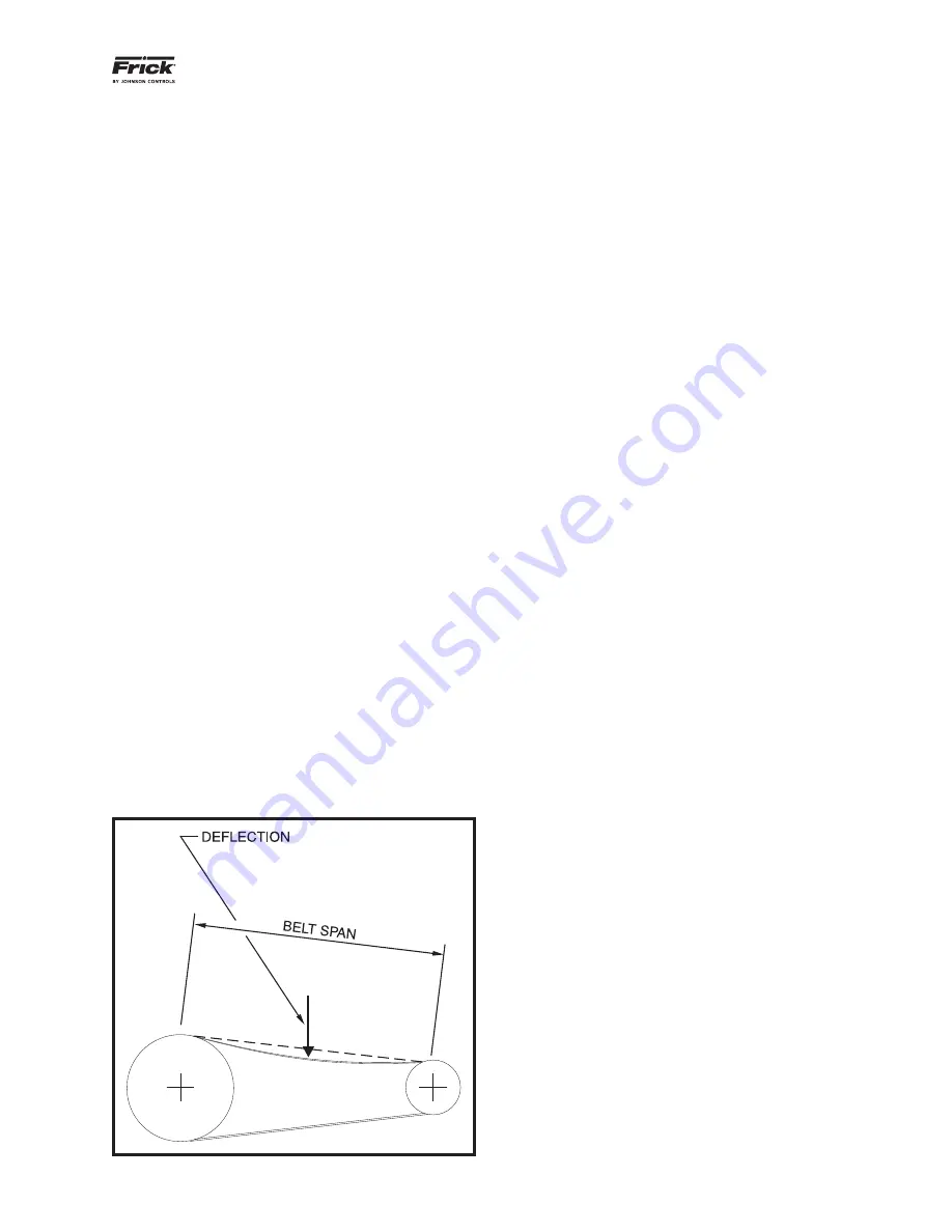
All belt tension measuring devices should include operating
instructions. These are spring-loaded devices that use a
hook to place tension on a stationary belt. Tension readings
are observed at a point where the belt defl ects a predeter-
mined distance. Tension is usually applied at the belt span’s
mid-point as measured between the tangent of belt contact
for both sheaves. Reference
Figure 4-5. Belt Tensioning
Schematic.
4.7 New Belt Run-in
During initial startup of new belts, a belt run-in procedure is
recommended. During start-up, follow these instructions:
During start-up, look and listen for unusual noise or vibra-
tion.
1. After shutting down and locking out the starter, check the
bearings and motor. If they feel hot, the belt tension may
be too tight.
2. Run the drive under full load for 24 hours of continuous
operation. Running the belts under full load allows them
to seat themselves into the grooves.
3. After running the drive, check the tension of the belts. Re-
tension to the recommended values. This run-in procedure
will reduce the future need for re-tensioning and will help
extend the life of the belts.
4.8 Coil
Assembly
An evaporative-cooled condenser’s operational readiness is
dependent on the condition of the coil. Coils that are dirty,
blocked from air-fl ow, or physically damaged may affect
overall heat transfer capability of the IDC to a signifi cant
degree.
Periodically conduct a visual inspection of the coil section
and refrigerant line connections. Remove any airborne debris
that may have collected on the face of intake louvers or on
the coils themselves. If separate air fi ltration exists prior to
the intake louvers, ensure that adequate “free area” exists
to meet intake-air CFM requirements.
Further need for cleaning or repair of an IDC coil should be
left to the judgement of a certifi ed or factory-trained service
person. Contact the local Frick representative if a coil or its
connections appears to have been signifi cantly damaged.
4.9 Water Makeup Requirements
At its rated capacity (given in tons), an IDC unit will evaporate
3 gallons/min per 100 tons.
When the water evaporates, any impurities remain. Recircu-
lating water fl ow then requires refreshing to prevent eventual
scale build up. A bleed-off valve is located on the spray pump
discharge line to bleed off an equal amount of water to that
evaporated. (3 GPM per 100 tons)
For conditions where the original water hardness is very high
or a large number of airborne contaminants may be washed
into the recirculating spray water, a higher bleed-off rate or
chemical treatment may be required. Consult a local water
treatment company for recommendations.
4.10 Water Treatment
If the condition of the water is such that constant bleed-off
will not control scale and/or control the recirculating water
pH level within the acceptable range listed below, chemical
treatment may be required. If a water treatment program
Figure 4-5. Belt Tensioning Schematic