NETWORK CONNECTIVITY
The EMCOMMS meter is compatible with both BACnet and Modbus networks. The meter is designed to automatically identify
the network baud rate, protocol type, serial formats and self-address for quick startup. Follow the
BACnet Network Connectivity
or
Modbus Network Connectivity
section for the steps required to connect the meter to an existing network.
To manually setup network parameters of the EMCOMMS meter, remove meter from the active network and utilize the
EMCOMMS
Series Configuration Tool.
MODBUS NETWORK CONNECTIVITY
Once the EMCOMMS meter has been connected to the RS-485
network, it will automatically detect Modbus traffic and begin
auto-configuration. The meter will detect and match baud rate,
parity and stop bits. Connect the meter to a Modbus network
through the following steps:
1. Wire the EMCOMMS meter to an existing Modbus network
utilizing the wiring diagrams in
Figure 4. EMCOMMS Meter
Wiring
.
2. Apply power to the meter.
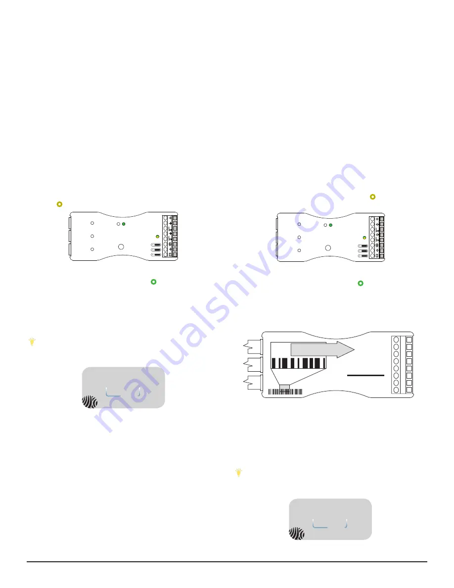
3. Meter will analyze the network traffic for the following
parameters: baud rate, serial format and protocol. During this
configuration, the RS485 LED
y
should display approximately
15-30 seconds of blinking activity in yellow
while the meter
configures itself to the network.
2
1
Setup Bu
�
on
Line Status
LED
Device
Status LED
CV
T
St
at
us
LE
Ds
RS485
Status LED
EMCOMMS
Figure 10: RS485 LED Activity
4. The RS485 LED
y
will appear green
after the meter has
sucessfully connected to the network. If the RS485 LED does
not appear green, see
Diagnostic Mode (Page 4)
.
5. The EMCOMMS meter ships with a default Modubs slave
address. To identify this address, add “100” to the last two digits
of the unique serial number printed on the label:
SN 123456
56
+100
156
3456
Figure 11: EMCOMMMS Meter Serial Number
The example meter in
Figure 11: EMCOMMS Meter Serial Number
would have a default Modbus slave address of 156.
To customize the Modbus slave address (along with other
network parameters) reference the
EMCOMMS Series Modbus
Protocol Guide
document or utilize the
EMCOMMS Series
Configuration Tool.
Tip: Customizing the Modbus slave address? Mark the new
address on the EMCOMMS meter label with a permanent
marker for a quick reference point:
12 t
o 30
VDC
1.5 W T
yp
24
VAC
Class 2
130 mA M
ax
Isola
ted
1500 V
rms
Read instructions
before installing
60 °C M
ax
on
off
P
WER
with
technology
address
Pulse Inputs
Johnson C
ontr
ols
ROG sensors only
EMCOMMS
120
511
511
Ì240042f
240042
Roland Versaworks Variable Data Printing:
Serial
Courier New, 6 pt, Left aligned
BarCode
Code 128, 22 pt, Left aligned
Serial2
Courier New, 6 pt Bold, Center aligned
BarCode2
Code 128, 22 pt, Center aligned
Date
Myriad Pro Light, 6 pt, Left aligned
R
L1
L2
L3
A
B
C
S
T
Device
Status
Line
Status
Setup
RS485
Status
Termination
MATERIAL:
ORACAL 651 SILVER GREY
INK:
ROLAND ESL3
ALTERNATES REQUIRE UL APPROVAL
B
C
A
D
4
1
2
3
5
4
1
2
3
5
B
C
A
D
Adobe Illustrator CC 2015
1 of 1
A
UPDATED
PAGE
SIZE
REV
PART NUMBER
9290 SW Nimbus Ave.
Beaverton, OR 97008
1-800-660-8864
Thursday, June 23, 2016
0A
141-0272
LABEL, EM, RS485
DESCRIPTION
BY
DATE
REV
Initial Release
DLE
0A
TBD
Figure 12: EMCOMMS Meter Address Label
BACNET NETWORK CONNECTIVITY
Once the EMCOMMS meter has been connected to the RS-485
network, it will automatically detect BACnet traffic and and
begin auto-configuration. The meter will detect and match
baud rate and identify an unused MAC address to occupy.
Connect the meter to a BACnet network through the following
steps:
1. Wire the EMCOMMS meter to an existing BACnet network
utilizing the wiring diagrams in
Figure 4. EMCOMMS Meter Wiring
.
2. Apply power to the meter.
3. Meter will analyze the network traffic for the following
parameters: baud rate, serial format, protocol and available
MAC address. During this configuration, the RS485 LED
y
should display approximately 15-30 seconds of blinking activity
in yellow
while the meter configures itself to the network.
2
1
Setup Bu
�
on
Line Status
LED
Device
Status LED
CV
T
St
at
us
LE
Ds
RS485
Status LED
EMCOMMS
Figure 8: RS485 LED Activity
4. The RS485 LED
y
will appear green
after the meter has
successfully connected to the network. If the RS485 LED does
not appear green, see
Diagnostic Mode (Page 4)
.
To customize the BACnet address and device ID (along with
other network parameters) reference the
EMCOMMS Series
BACnet Protocol Guide
document or utilize the
EMCOMMS Series
Configuration Tool.
Tip: Customizing the MAC address? Mark the new address
on the EMCOMMS meter label with a permanent marker for a
quick reference point:
12 t
o 30
VDC
1.5 W T
yp
24
VAC
Class 2
130 mA M
ax
Isola
ted
1500 V
rms
Read instructions
before installing
60 °C M
ax
on
off
P
WER
with
technology
address
Pulse Inputs
Johnson C
ontr
ols
ROG sensors only
EMCOMMS
120
511
511
Ì240042f
240042
Roland Versaworks Variable Data Printing:
Serial
Courier New, 6 pt, Left aligned
BarCode
Code 128, 22 pt, Left aligned
Serial2
Courier New, 6 pt Bold, Center aligned
BarCode2
Code 128, 22 pt, Center aligned
Date
Myriad Pro Light, 6 pt, Left aligned
R
L1
L2
L3
A
B
C
S
T
Device
Status
Line
Status
Setup
RS485
Status
Termination
MATERIAL:
ORACAL 651 SILVER GREY
INK:
ROLAND ESL3
ALTERNATES REQUIRE UL APPROVAL
B
C
A
D
4
1
2
3
5
4
1
2
3
5
B
C
A
D
Adobe Illustrator CC 2015
1 of 1
A
UPDATED
PAGE
SIZE
REV
PART NUMBER
9290 SW Nimbus Ave.
Beaverton, OR 97008
1-800-660-8864
Thursday, June 23, 2016
0A
141-0272
LABEL, EM, RS485
DESCRIPTION
BY
DATE
REV
Initial Release
DLE
0A
TBD
Figure 9: EMCOMMS Meter Address Label
EMCOMMS Series Meter - Installation Instructions
3


