3. To detach the left-hand side of the terminal block,
position the flat blade underneath the terminal
block to the left, and push down the screwdriver
handle. When you do this, you are using the
screwdriver as a lever to pry up the terminal block.
4. To detach the right-hand side of the terminal block,
position the flat blade underneath the terminal
block to the right, and push down the screwdriver
handle.
5. If necessary, repeat steps 3 and 4 until the terminal
block is removed.
Setting the End-of-Line (EOL) switch
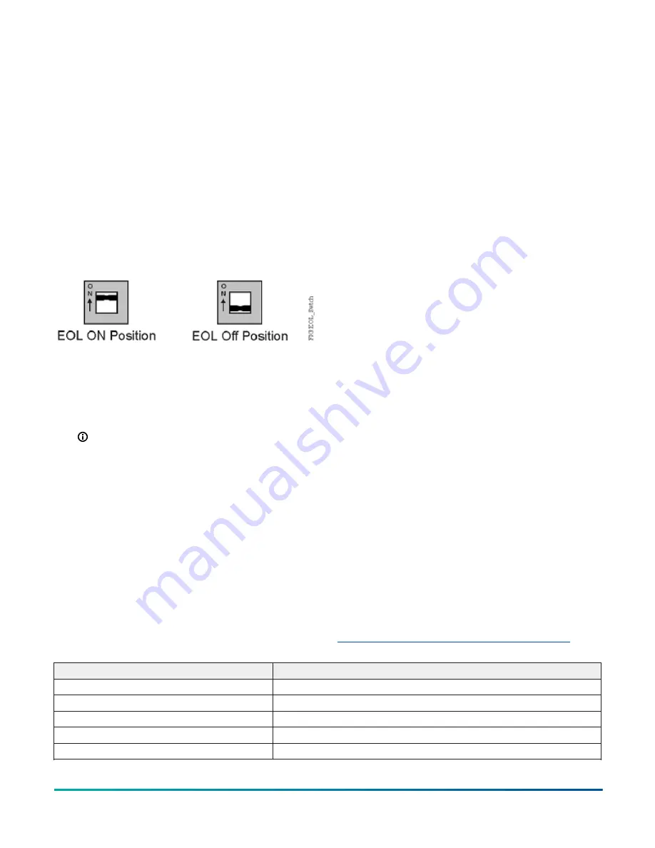
Each CVM controller has an EOL switch, which, when
set to ON (up), sets the CVM controller as a terminating
device on the bus. See
location. The default EOL switch position is OFF (down).
Figure 12: End-of-Line Switch Positions
To set the EOL switch on a CVM controller, complete the
following steps:
1. Determine the physical location of the controller on
the FC bus.
2. Determine if the controller must be set as a
terminating device on the bus.
Note:
For detailed information about EOL
termination rules and EOL switch settings on
FC buses, refer to the
MSTP Communications Bus
Technical Bulletin (LIT-12011034)
.
3. If the controller is a terminating device on the FC
Bus, set the EOL switch to ON. If the controller is not
a terminating device on the bus, set the EOL switch
to OFF.
When a controller is connected to power with its EOL
switch set to ON, the amber EOL LED on the controller
cover is illuminated.
Input and output wiring validation
The CVM controllers ship with a cooling only, warm or
cool adjust application loaded by default. You can use this
default application to perform wiring verification using
the MAP Gateway or the MS-DIS1710-0 local controller
display.
To perform wiring validation, ensure that you set the
rotary switches to the desired address and wire the input
and output terminals. Apply power to the CVM controller.
The Fault LED behaves the same as it does during normal
application load. When the Fault LED turns off, connect
to the device with either a MAP Gateway or MS-DIS1710-0
Local Display to view the points in the controller.
Commissioning equipment controllers
To commission the CVM03050 controller, use the following
procedure:
1. With the desired application loaded in the controller,
commission the VAV Box. Refer to the
Controller Tool
Help (LIT-12011147)
.
2. Perform airflow balancing on the VAV box.
Refer to the
VAV Balancing Tool Technical Bulletin
(LIT-12011087)
.
3. Perform commissioning checkout procedures. Refer
to the
Controller Tool Help (LIT-12011147)
.
You commision MS/TP equipment controllers with the
CCT software using either MAP Gateway, a ZFR wireless
dongle, or in passthrough mode. When the controller
is configured to use the N2 protocol, you must use the
MAP Gateway at the SA Bus. Wireless connections are not
supported in N2 mode. These connection options require
additional hardware listed in Table 13.
Firmware package file
The MS-FCP-0 equipment controller firmware package
files are required for CCT to configure and commission
the controllers. The firmware package files also allow you
to upgrade an existing controller to the latest firmware
release available for that controller.
Beginning at CCT Release 13, the firmware package files
are orderable separately; they are not included with CCT.
They are obtained from the
Metasys
software licensing
portal, and are loaded and licensed on the computer/
server that is running CCT.
For additional information about the firmware
package files, refer to the
CCT Installation Instructions
(LIT-12011259)
.
Setting a preloaded application
You can configure a CVM controller to use one of the
14 preloaded applications using the MAP Gateway
release 5.1 or later. Refer to Table 9 for the list of
preloaded applications. The CVM controllers ship with the
Cooling Only W/C Adjust application set by default. For
instructions on setting a different preloaded application
using the MAP Gateway, refer to the uLearn training video
Setting a CVM Preloaded Application using the MAP
Table 9: CVM Preloaded Standard Applications
Application Name
Description
Cooling Only W/C Adj
Single Duct Cooling Only, Warm/Cool Adjust
Cooling Only SP Adj
Single Duct Cooling Only, Setpoint Adjust
Incr HW Reheat W/C Adj
Single Duct Incremental Hot Water Reheat, Warm/Cool Adjust
Incr HW Reheat SP Adj
Single Duct Incremental Hot Water Reheat, Setpoint Adjust
Elec Reheat 3 Stg W/C Adj
Single Duct Electric Staged Reheat, 3 Stages, Warm/Cool Adjust
M4-CVM VAV Box Controllers Installation Guide
15


