background image

872678-UIM-C-0213

4

Johnson Controls Unitary Products

PRECAUTIONS DURING BRAZING OF LINES

All outdoor unit and evaporator coil connections are copper-to-copper
and should be brazed with a phosphorous-copper alloy material such
as Silfos-5 or equivalent. DO NOT use soft solder. The outdoor units
have reusable service valves on both the liquid and vapor connections.
The total system refrigerant charge is retained within the outdoor unit
during shipping and installation. The reusable service valves are pro-
vided to evacuate and charge per this instruction.

Serious service problems can be avoided by taking adequate precau-
tions to assure an internally clean and dry system.

PRECAUTIONS DURING BRAZING SERVICE VALVE

Precautions should be taken to prevent heat damage to service valve
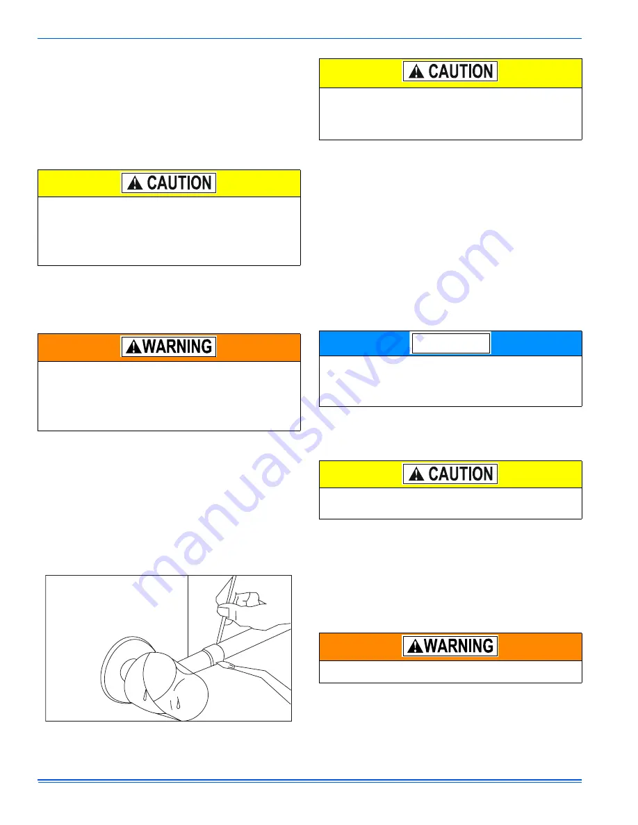
by wrapping a wet rag around it as shown in Figure 4. Also, protect all
painted surfaces, insulation, and plastic base during brazing. After braz-
ing, cool joint with wet rag.

Valve can be opened by removing the plunger cap and fully inserting a
hex wrench into the stem and backing out counter-clockwise until valve
stem just touches the chamfered retaining wall.

Connect the refrigerant lines using the following procedure:

1.

Remove the cap and Schrader core from both the liquid and vapor
service valve service ports at the outdoor unit. Connect low pres-
sure nitrogen to the liquid line service port.

2.

Braze the liquid line to the liquid valve at the outdoor unit. Be sure
to wrap the valve body with a wet rag. Allow the nitrogen to con-
tinue flowing.

3.

Carefully remove the plugs from the evaporator liquid and vapor
connections at the indoor coil.

4.

Braze the liquid line to the evaporator liquid connection. Nitrogen
should be flowing through the evaporator coil.

5.

Slide the grommet away from the vapor connection at the indoor
coil. Braze the vapor line to the evaporator vapor connection. After
the connection has cooled, slide the grommet back into original
position.

6.

Protect the vapor valve with a wet rag and braze the vapor line
connection to the outdoor unit. The nitrogen flow should be exiting
the system from the vapor service port connection. After this con-
nection has cooled, remove the nitrogen source from the liquid fit-
ting service port.

7.

Replace the Schrader core in the liquid and vapor valves.

8.

Go to SECTION IV or SECTION V for orifice or TXV installation
depending on application.

9.

Leak test all refrigerant piping connections including the service
port flare caps to be sure they are leak tight. DO NOT OVER-
TIGHTEN (between 40 and 60 inch - lbs. maximum).

10. Evacuate the vapor line, evaporator, and liquid line to 500 microns

or less.

11.

Replace cap on service ports. Do not remove the flare caps from
the service ports except when necessary for servicing the system.

12. Release the refrigerant charge into the system. Open both the liq-

uid and vapor valves by removing the plunger cap and with an
allen wrench back out counter-clockwise until valve stem just
touches the chamfered retaining wall. If the service valve is a ball
valve, use a cresent wrench to turn valve stem one-quater turn
counterclockwise to open. Do not overturn or the valve stem may
break or become damaged. See “PRECAUTIONS DURING
BRAZING SERVICE VALVE”.

13. Replace plunger cap finger tight, then tighten an additional 1/12

turn (1/2 hex flat). Cap must be replaced to prevent leaks.

See "System Charge” section for checking and recording system
charge.

Supplied with the outdoor unit is a Schrader Valve Core and Orifice for
highest sales volume indoor coil. The valve core must be installed in
equalizer fitting of the indoor coil.

 Dry nitrogen should always be supplied through the tubing while it
is being brazed, because the temperature required is high enough
to cause oxidation of the copper unless an inert atmosphere is pro-
vided. The flow of dry nitrogen should continue until the joint has
cooled. Always use a pressure regulator and safety valve to insure
that only low pressure dry nitrogen is introduced into the tubing.
Only a small flow is necessary to displace air and prevent oxidation.

This is not a backseating valve. The service access port has a
valve core. Opening or closing valve does not close service access
port.
 If the valve stem is backed out past the chamfered retaining wall,
the O-ring can be damaged causing leakage or system pressure
could force the valve stem out of the valve body possibly causing
personal injury.

 FIGURE 4:  

Heat Protection

Do not install any coil in a furnace which is to be operated during
the heating season without attaching the refrigerant lines to the coil.
The coil is under 30 to 35 psig inert gas pressure which must be
released to prevent excessive pressure build-up and possible coil
damage.

Line set and indoor coil can be pressurized to 250 psig with dry
nitrogen and leak tested with a bubble type leak detector. Then
release the nitrogen charge.
Do not use the system refrigerant in the outdoor unit to purge or
leak test.

 Do not connect manifold gauges unless trouble is suspected.
Approximately 3/4 ounce of refrigerant will be lost each time a stan-
dard manifold gauge is connected.

Never attempt to repair any brazed connections while the system is
under pressure. Personal injury could result.

NOTICE

Summary of Contents for 13 SEER - GCGD

Page 1: ...tion to the signal words DANGER WARNING or CAUTION DANGER indicates an imminently hazardous situation which if not avoided will result in death or serious injury WARNING indicates a potentially hazardous situation which if not avoided could result in death or serious injury CAUTION indicates a potentially hazardous situation which if not avoided may result in minor or moderate injury It is also us...

Page 2: ...sing unit combination with the appropriate metering device 2 Change out of the line set when replacing an R 22 unit with an R410 A unit is highly recommended to reduce cross contamina tion of oils and refrigerants 3 If change out of the line set is not practical then the following pre cautions should be taken Inspect the line set for kinks sharp bends or other restrictions and for corrosion Determ...

Page 3: ...to avoid sharp bends which may cause a restriction 2 The lines should be installed so that they will not obstruct service access to the coil air handling system or filter 3 Care must also be taken to isolate the refrigerant lines to minimize noise transmission from the equipment to the structure 4 The vapor line must be insulated with a minimum of 1 2 foam rub ber insulation Armaflex or equivalent...

Page 4: ...VER TIGHTEN between 40 and 60 inch lbs maximum 10 Evacuate the vapor line evaporator and liquid line to 500 microns or less 11 Replace cap on service ports Do not remove the flare caps from the service ports except when necessary for servicing the system 12 Release the refrigerant charge into the system Open both the liq uid and vapor valves by removing the plunger cap and with an allen wrench bac...

Page 5: ...er fitting and an additional 1 3 turn to seal 7 Install the TXV bulb to the vapor line near the equalizer line using the bulb clamp s furnished with the TXV assembly Ensure the bulb is making maximum contact a Bulb should be installed on a horizontal run of the vapor line if possible The bulb should be installed on top of the line b If bulb installation is made on a vertical run the bulb should be...

Page 6: ...he default subcool ing is 10 F 1 Set the system running in cooling mode by setting the thermostat at least 6 F below the room temperature and operate system for at least 10 15 minutes 2 Refer to the technical guide for the recommended indoor airflow and verify it is correct it should be about 400 SCFM per ton 3 Measure and record the indoor wet bulb WB and the outdoor ambient dry bulb DB temperatu...

Page 7: ...ply connections TABLE 2 R 410A Saturation Properties TEMP F PRESSURE PSIG TEMP F PRESSURE PSIG TEMP F PRESSURE PSIG TEMP F PRESSURE PSIG TEMP F PRESSURE PSIG 45 130 60 170 75 217 90 274 105 341 46 132 61 173 76 221 91 278 106 345 47 135 62 176 77 224 92 282 107 350 48 137 63 179 78 228 93 287 108 355 49 140 64 182 79 232 94 291 109 360 50 142 65 185 80 235 95 295 110 365 51 145 66 188 81 239 96 29...

Page 8: ... unit and thermostat To eliminate erratic operation seal the hole in the wall at the ther mostat with permagum or equivalent to prevent air drafts affecting the operation of in the thermostat NOTICE FIGURE 8 Typical Field Wiring Air Handler Electrical Heat Single Phase ALL FIELD WIRING TO BE IN ACCORDANCE WITH ELECTRIC CODE NEC AND OR LOCAL CODES POWER WIRING CONTACTOR TERMINALS COIL GND LUG C Y R...

Page 9: ...r electric heat on thermostat is not necessary MA SHP AHP ID MODELS Other Part Numbers SAP Legacy 265902 031 09167 2 Part Numbers SAP Legacy 159480 031 09156 1 COM 24 Volt Common R 24 Volt Hot W2 Second Stage Heat O Reversing Valve Energized in Cool X L Malfunction Light HUM Humidity Switch Open on Humidity Rise PSC AIR HANDLER CONTROL G Fan PSC AIR HANDLER 1 EAC 24 VAC out Electronic Air Cleaner ...

Page 10: ...r Y1 Single Stage Compressor Y Y2 Second or Full Stage Compressor W1 First Stage Heat Y Full Stage Compressor G Fan BP11C50124 BN11C01124 DP11C40124 DN11C00124 THERMOSTAT RH 24 Volt Hot Heat XFMR RC 24 Volt Hot Cool XFMR W Full Stage Heat Selection of GAS ELEC switch on thermostat is not necessary C 24 Volt Common Y Full Stage Compressor G Fan BN11C00124 THERMOSTAT RH 24 Volt Hot Heat XFMR RC 24 V...

Page 11: ...ull Stage Heat Clipping Jumper W914 for electric heat on thermostat is not necessary 24VAC Humidifier Optional C 24 Volt Common Y Compressor SINGLE STAGE AIR CONDITIONER Y Compressor Contactor SINGLE STAGE AIR CONDITIONER SINGLE STAGE AIR CONDITIONER G8C L Y M 8S G 9F G 8 9 S ID MODELS G T GLS TG 8 9 S LF8 GF 8 9 C 24 Volt Common R 24 Volt Hot W Full Stage Heat SINGLE STAGE PSC FURNACE G Fan SINGL...

Page 12: ...ermostat is not necessary C 24 Volt Common Y Full Stage Compressor G Fan BN11C00124 THERMOSTAT RH 24 Volt Hot Heat XFMR RC 24 Volt Hot Cool XFMR W Full Stage Heat Thermostat Installer Setup 1 System Type must be set to 0 C 24 Volt Common Thermostat Installer Setup 15 Compressor Protection must be set to 5 External Humidistat Optional Open on Humidity Rise G8C L Y M 8S G 9F G 8 9 S ID MODELS G T GL...

Page 13: ...eration and maintenance of all other system components MAINTENANCE 1 Dirt should not be allowed to accumulate on the outdoor coils or other parts in the air circuit Clean as often as necessary to keep the unit clean Use a brush vacuum cleaner attachment or other suitable means 2 The outdoor fan motor is permanently lubricated and does not require periodic oiling 3 If the coil needs to be cleaned u...

Page 14: ...872678 UIM C 0213 14 Johnson Controls Unitary Products SECTION X WIRING DIAGRAM FIGURE 14 Wiring Diagram Single Phase ...

Page 15: ...872678 UIM C 0213 Johnson Controls Unitary Products 15 FIGURE 15 Wiring Diagram Three Phase 2 5 5 Tons 412217 ...

Page 16: ...CED WITH TYPE 105 C THERMOPLASTIC OR ITS EQUIVALENT WIRING MUST CONFORM TO NATIONAL AND LOCAL CODES HPS HIGH PRESSURE SWITCH LP LOW PRESSURE SWITCH LAP LOW AMBIENT PRESSURE SWITCH CCH CRANKCASE HEATER CC CONTACTOR COIL ASCT ANTI SHORT CYCLE TIME DANGER SHOCK HAZARD TURN OFF ELECTRICAL POWER BEFORE SERVICING TO PREVENT POSSIBLE DAMAGE TO THE EQUIPMENT AND POSSIBLE PERSONAL INJURY CAUTION TO PREVENT...

Page 17: ...if applicable Electrical Line Voltage Outdoor Unit Model Outdoor Unit Serial Filter Thermostat Accessories Filter Location s Connections Per Installation Instructions and Local Codes Gas piping is connected if applicable Supply plenum and return ducts are connected and sealed Filter Size Vent system is connected if applicable Thermostat wiring complete Heat anticipator is set to the recommended va...

Page 18: ...ith the owner s manual Explain thermostat use and programming if applicable to owner Cycle Test Operate the unit through several heating cycles if applicable from the thermostat noting and correcting any problems Operate the unit through continuous fan cycles from the thermostat noting and correcting any problems Operate the unit through a cooling cycles noting and correcting any problems COOL ADJ...

Reviews: