background image

5

Sales/Replacement Telephone 01604 762881

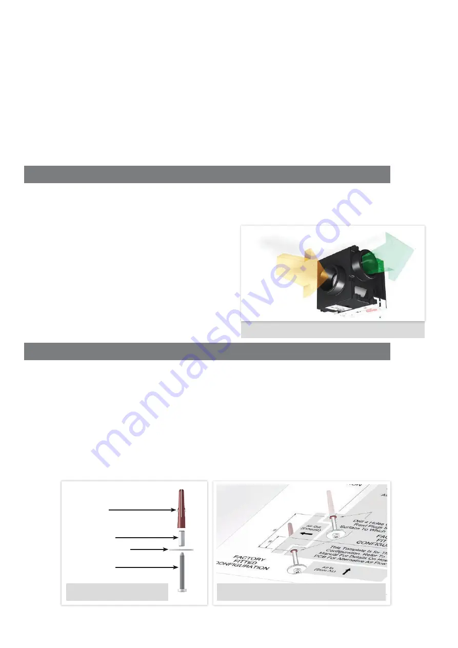
FIGURE 2. AIRFLOW THROUGH UNIT


BASE MOUNTED 

- with ducting connected horizontally and exhaust exiting through a wall or roof 

terminal. If used in this position make sure there is an adequate working area with a secure base. 


VERTICALLY MOUNTED

 - when using flexible ducting ensure the connections are made, with the 

correct radius bends.


SUSPENDED

 - Ensure ductwork is supported throughout it’s length. 

NOTE: 

   A clear space of at least 50mm below and 230mm to the sides is required to allow the cover to be 

removed and provide sufficient access for maintenance.

7.3  

SPIGOTS

7.3.1    The unit has one stale air inlet spigot and one exhaust air outlet spigot. 
7.3.2 

The spigot has and internal diameter of 100mm and 125mm outer diameter.

7.4 

HANDING

7.4.1 

If Q-Vent CE50 air flow configuration is required to be handed opposite to the factory default see 
publication Number ZZ1518 for the correct change procedure. 

8. 

DUCT & DUCT CONNECTIONS

8.1   

For satisfactory operation of the unit, ensure ducting used is as detailed on the design drawing. Any deviation 
from the design drawing could lead to noise increase on boost.

NOTE:

   In situations where it is either not possible or not desirable to use 125mm ducting on the stale air outlet. 

100mm ducting can be used but it MUST be noted, in ‘BOOST’ mode, it might increase noise levels.

8.2


Where 125mm rigid ducting is used it must fit on the 
125mm (outer) spigots and for 100mm ducting on the 
100mm (inner) spigots.

IMPORTANT:

 When inserting 100mm ducting into the spigot, 

ensure it is no longer the 45mm.

8.3 

Where rigid ducting is used, it should be installed using 
the least number of fittings to minimise resistance to air 
flow. Where possible, final connection from the rigid 
ducting to grilles and the unit should be made with a 
flexible connection.

8.4 

The exhaust air must exit to outside through either a 
wall or a roof and must be protected by a wall baffle or 
recognised roof terminal.


9. 

INSTALLATION INSTRUCTIONS

IMPORTANT: The installation should be carried out by a competent person in accordance with the appropriate 
authority and conforming to all the statutory and governing regulations.
NOTE:  

The enclosure of this product is made from EPP. Failure to use the correct screw spacers or the over 
tightening of any screws may damage the appliance. 

9.1 

Identify the directional airflow requirements and determine if the factory configuration is suitable. If not, then 
refer to document ZZ1518 to re-configure to an alternative airflow.

9.2 

Place the template in the position and drill the 4 fixing holes. Take into consideration the material you are 
drilling into and use appropriate screws and fixings to support the unit. Use the rawl plugs where necessary. 


Use the M5 x 25mm washers and screw spacers provided. Alternative fixings may be used if deemed more 
suitable to the site requirements at the time of installation. These are not included.

9.4 

Fix the 2 screws, washers and 16mm spacers into the Air Out/Exhaust fixing holes as shown on the template. 
DO NOT OVER TIGHTEN.

RAWL PLUG

16mm SPACER

M5 x 25mm WASHER

FIXING SCREW

EXHAUST 

AIR OUT

STALE AIR IN

FIGURE 3. FIXING SCREW

FIGURE 4. TEMPLATE & FIXING SCREW

Summary of Contents for Q-VENT CE50

Page 1: ...www johnsonandstarley co uk Publication No ZZ 1516 3 May 2016 Q VENT CE50 Central Extract System INSTALLATION COMMISSIONING SERVICING INSTRUCTIONS ...

Page 2: ...lations 4 5 Safety Electrical Water Information 4 6 Technical Data 4 7 Preparation Positioning 4 Ducting Information Positioning The Unit Spigots Handing 8 Duct Duct Connections 5 9 Installation Instructions 5 10 Electrical 6 Electrical Wiring Options Over Heat Protection 11 Specific Fan Performance 7 12 Sound Spectrum 7 13 Circuit Diagram 8 14 Commissioning 8 Pre Commissioning Check Installer Mod...

Page 3: ...ir is discharged to outside via a single duct and grille 3 2 The case is constructed from EPP an expanded polypropylene 5 4 3 2 2 7 9 14 1 8 8 9 11 6 13 12 10 1 ITEM DESCRIPTION QTY 1 Q Vent CE50 1 2 Fixing Kit 1 M5 x 25mm Washers 4 No 8 x 50mm Wood Screws 4 Rawl Plugs 4 16mm Screw Spacers 2 3 Template 1 4 Installation Users Instructions 1 FEATURES 7 LED Light 8 Main Supply Cable 9 4 Way Terminal ...

Page 4: ...When installing the unit take care not to damage electrical or other hidden utilities 5 1 9 Exhaust air must be vented to the outside 5 1 10 The fan motor is fitted with sealed for life bearings and therefore does not require lubrication 6 TECHNICAL DATA 7 PREPARATION POSITIONING 7 1 DUCT INFORMATION 7 1 1 It is an advantage to have all the compatible ductwork already installed and ready to connec...

Page 5: ...When inserting 100mm ducting into the spigot ensure it is no longer the 45mm 8 3 Where rigid ducting is used it should be installed using the least number of fittings to minimise resistance to air flow Where possible final connection from the rigid ducting to grilles and the unit should be made with a flexible connection 8 4 The exhaust air must exit to outside through either a wall or a roof and ...

Page 6: ...r the unit 10 5 ELECTRICAL WIRING OPTIONS 10 5 1 A facility is included which boosts the fan duty as required The boost can be achieved by the following method 10 5 2 Connecting black wire from the mains lead to an external 230V AC live source e g bathroom double pole light switch or humidistat 10 6 OVER HEAT PROTECTION 10 6 1 The fan motor is fitted with standard thermal Overload Protection This ...

Page 7: ...M 11 SPECIFIC FAN PERFORMANCE NOTE Performance graphs shown for two extracts kitchen bathroom FIGURE 7 FAN PERFORMANCE GRAPH TABLE 2 SPECIFIC FAN POWER NAME SPF EXTRACT RATE Kitchen 1 0 25 W L s 21 L s Kitchen 2 0 28 W L s 29 L s Kitchen 3 0 35 W L s 37 L s Kitchen 4 0 42 W L s 45 L s ...

Page 8: ...w for situations where the unit is not taken out of installer mode 14 2 1 To activate Installer Mode Isolate the electrical supply wait 5 seconds and reconnect 14 2 2 When installer mode is ready the red LED indicator will start flashing every second Now extract and supply fans can be adjusted 14 2 3 To set trickle see paragraph 14 3 4 14 2 4 To set boost see paragraph 14 4 4 14 2 5 Once both sett...

Page 9: ... 2 Activate Installer Mode 14 4 3 To adjust the BOOST setting turn RV1 clockwise to increase the airflow rate and anti clockwise to decrease the airflow rate to required setting 14 4 4 When the boost airflow is set to the desired rate exit Installer Mode IMPORTANT NOTE After fan speed setting has been completed and the unit is no longer in installer mode the RV1 Fan adjust boost overrun is used to...

Page 10: ... needed telephone Johnson Starley Ltd 01604 762881 for further information 16 USERS INSTRUCTIONS 16 1 Hand the User Instructions to the householder explain and demonstrate how to use the unit 16 2 Show how the unit is turned on at the fused spur 16 3 The unit will now commence extraction at the minimum set speed 16 4 If the unit is fitted with remote automatic boost switch demonstrate how the boos...

Page 11: ...E 165 Q VENT CE50 EXPLODED DIAGRAM 18 EXPLODED DIAGRAM 19 SPARE LIST ITEM PART No DESCRIPTION QTY 1 1000 0525605 PCB Assembly 1 2 CE50 0520005 Fan Assembly 1 3 a b 1000 0028825 Outer Fan Casing 2 part set 1 4 CE50 0105005 PCB Cover Plate 1 2 1 3a 3b 4 ...

Page 12: ... sales johnsonandstarley co uk marketing johnsonandstarley co uk Reception Customer Service 01604 762881 Fax 01604 767408 In the interest of continuous development Johnson Starley reserve the right to change specifications without prior notice Anniversary 1922 2012 ...

Reviews: