4.3
WALL MOUNTING:
Prior to wall mounting, remove the fixing template from the packaging and decide whether the appliance is to be L.H or
R.H mounted. The handing of the mounting refers to the side of the heater to be affixed to the wall, utilizing the
mounting bracket provided.
4.3.1
Replace the 2 x 13mm No 8 case/body fixing screws from the side of the heater to be affixed to the wall with 2 x
20mm No 8 screws (provided separately), ensuring these screws are not fully tightened.
4.3.2
Fit and secure the mounting bracket to heater using screws fitted at 4.3.1, ensuring the free slots on the mounting
bracket are to the front of the heater.
4.3.3
Using the appropriate template, mark the position of the 4 x fixing screws on the wall where the heater is to be
fitted, ensuring that the heater will be level when fitted.
4.3.4
Fix the retaining bracket to the wall using suitable wall plugs and screws.
4.3.5
Plug and partially insert 2 x screws to accept the mounting bracket.
4.3.6
Locate the appliance rear foot in the retaining bracket and engage the 2 x slots in the mounting bracket onto the
screws fitted at 4.3.5.
4.3.7
Ensuring that the appliance is level, secure the mounting bracket fixing screws.
4.4
FLUE INSTALLATION:
The flue pipe is to be installed in accordance with the guidelines detailed in para 3.5.
4.4.1
Ensure that a minimum length of 600mm (24in) of vertical flue is fitted directly above the draught diverter
wherever possible.
4.4.2
Ensure that a split collar is fitted in the flue within the 600mm (24in) vertical flue, preferably at or above the
mid point, to enable draught diverter removal.
Note: If a flue pipe conforming to BS715 is used, a suitable flue adaptor ( not included) must be fitted
.
4.5
WATER CONNECTIONS:
4.5.1
Connect flow and return pipes as required, in accordance with the guidelines detailed in Sect 3.6. To facilitate
subsequent dismantling of the heat exchanger, use union fittings at the point of connection to the appliance.
Ensure that return pipe work does not restrict access to the thermostat phial.
4.5.2
Prior to installation of the pump (if required), flush the system thoroughly ensuring that all valves are open.
4.6
BURNER AND CONTROLS ASSEMBLY FITTING:
4.6.1
Fit Burner and Control assembly to appliance, ensuring that the square lug to the rear of the assembly engages
into the locating bracket, and secure using the mounting screw ensuring that the screw is also used to secure the
capillary clip.
4.6.2
Insert thermostat phial fully into flow pocket and secure using thermostat retaining plug.
4.7
GAS CONNECTIONS:
4.7.1
Connect a suitable gas supply to the appliance via the union service cock supplied. Ensure that the pipe work
does not cause obstruction for Burner and Control assembly removal.
4.7.2
Test the gas installation for gas soundness, and purge in accordance with BS6891.
4.8
FINAL ASSEMBLY:
4.8.1
Connect ignition lead to Piezo unit.
4.8.2
Fix lighting instruction label to exposed side of the appliance.
5.
COMMISSIONING
5.1
With the pump fitted (if required), fill the water circulation system, clear any air locks and check for water soundness.
5.2
Remove Multifunctional control Temperature/Control knob, (this is a push fit only)
5.3
Ensure the Multifunctional control Pilot adjusting screw is fully out, (approximately 5 full turns counterclockwise from
fully in) indicated by a slight restriction when turned counterclockwise.
6
5.4
WATER TEMPERATURE SETTING FOR INDIRECT SYSTEMS:
Note: Thermostats are factory set to a temperature of 60°C (140°F), which is suitable for DIRECT and should NOT
be exceeded for this type of system. For INDIRECT systems, removal of stop screws situated on the temperature
control mechanism allows the Temperature Control to be set beyond the 60°C limit.
5.4.1
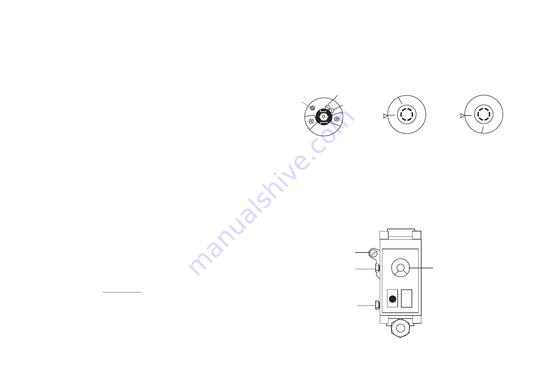
Referring to Figs. 4, identify stop screws 1 and 2.
5.4.2
Dependant upon the required water temperature, remove:
a.
Stop screw 1 to provide a maximum temperature of 68
°
C (155
°
F), or,
b.
Stop screws 1 and 2 to provide a maximum temperature of 7
7°
C (170
°
F).
5.4.3
Refit Multifunctional control Temperature/Control knob, ensuring that it fully engages on the valve spindle.
Fig. 5
Multifunctional control Component Identification
7
Fig. 4
Water Temperature Control Settings
5.5
GAS PRESSURE SETTING:
5.5.1
Referring to fig. 5, remove Inlet Pressure Test Point cover and connect Gas Pressure Test Gauge.
5.5.2
Turn the gas supply on at the gas service cock.
5.5.3
Referring to lighting instruction label, ignite the pilot burner and ensure the pilot flame envelopes the
thermocouple tip, adjusting the Pilot Adjusting screw if necessary.
Note: If the pilot flame cannot be set using the Pilot Adjustment screw, the pilot burner assembly must
be replaced.
5.5.4
Referring to Fig. 5 and Table 1 (para 2.1), set Multifunctional control Pressure Adjuster to provide the required
setting pressure for the installation.
Stop screw 2
Stop screw 1
Fig. 4a
Stop screw positions
Fig. 4b
Minimum Setting 60ºC
Fig. 4c
Maximum Setting 77ºC
Pilot
Adjustment
Sit
off
HOT
*
PRESSURE
ADJUSTMENT
SCREW
OUTLET
PRESSURE
TEST POINT
INLET
PRESSURE
TEST POINT
TEMPERATURE
CONTROL
Sit
OFF
HOT
OFF
HOT
Sit


