background image

2.5

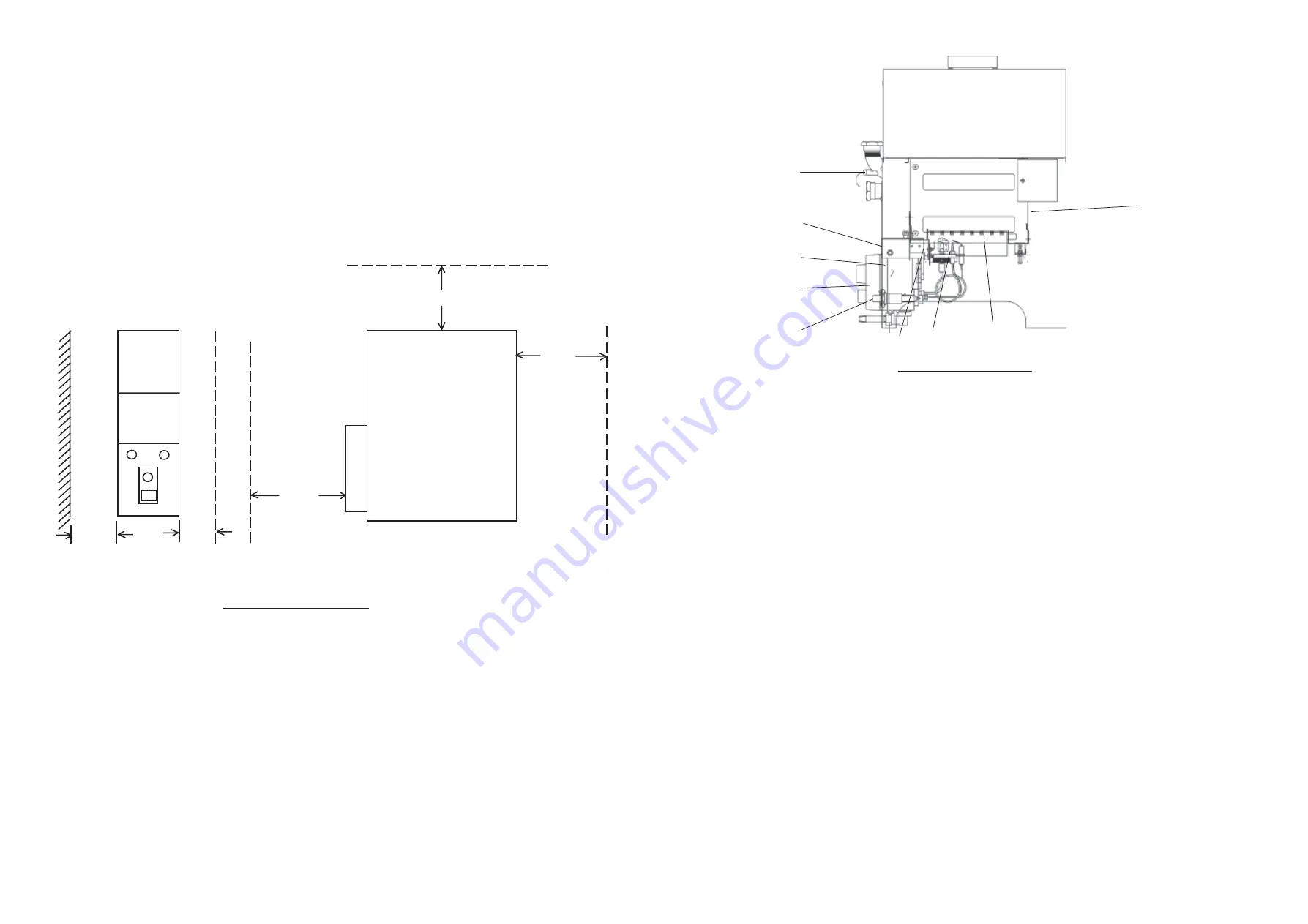
INSTALLATION AND CLEARANCES:

IMPORTANT: Care must be taken to ensure that adequate space is available at the front and ‘open’ side of the
heater for installation purposes.

2.5.1

Minimum clearance for combustion:
Front: 25mm (1in) from controls cover.
Sides: 16mm (

5

/

8

in) from side nearest to wall, 13mm (

1

/

2

in) from open side to any cylindrical obstruction

(i.e.. Hot water cylinder)

Note:

 If these minimum side clearances are to be adopted, special care must be

taken in the compartment construction to permit access to appliance mountings.

Rear:

100mm (4in).

Base:

Nil. The appliance may be floor mounted on noncombustible material.

2.5.2

Minimum clearance for servicing:
Front: 300mm (12in).
Side:

200mm (8in).

Note:


Flow and return pipes may be routed over the top of the heater, provided adequate access is available for

heat exchanger cleaning.

2

16mm

13mm

WALL SIDE

OPEN SIDE

100mm

200mm

300mm

FRONT

REAR

Fig. 1

Minimum clearances for JANUS 6/30

3.

GENERAL REQUIREMENTS

3.1

RELATED DOCUMENTS (refer to current issues).

This appliance MUST BE installed in accordance with the relevant requirements of the Gas Safety (Installation and
Use) Regulations, local Building Regulations,  and the Bye-laws of the local Water Company. It should also be in
accordance with any relevant requirements of the local Gas Region and Local Authority, and the relevant
recommendations of the following British Standard Codes of Practice:
BS 6798:

Specification for installation of gas fired hot water boilers of rated input not exceeding 60kW.

BS5546:

Installation of gas hot water supplies for domestic purposes (2

nd 

family gasses).

BS5440 Pt. 1: Flues.
BS5440 Pt. 2 Air supply.
BS6891:

Installation of low pressure gas pipe work up to 28mm (R1) in domestic premises.

BS6700:

Design, Installation, testing and maintenance of services supplying water for domestic use within
buildings and their curtilages.

3.2

LOCATION:

3.2.1

The location chosen for the circulator must permit the provision of a satisfactory flue and termination, an
adequate air supply for combustion purposes, and an adequate space for servicing and air circulation around
the appliance. 

The JANUS  6/30 must not be installed in a room containing a bath or shower, or either a

bedroom or a bed-sitting room.

11

2

3

6

4

1

5

7

8

9

9.

SHORT  LIST OF SPARES

Key

G.C. No

J&S Part No

Description

Qty

1

242 279

S00102

Main Body Assembly

1

2

793 243

JAN6/30/062

Burner and Controls Assembly (comprising of)

1

3

244 878

S00301

Multifunctional Control Mini SIT

1

381 670

S00260

‘O’ Ring Seal

1

4

384 615

BOS 00562

Burner Arm

1

5

JAN3-0704000

Pilot burner mounting bracket

1

6

379 874

1000-0704265

Pilot Burner Assembly

1

1000-0704320

Pilot Gas Feed Pipe

1

397 819

1000-0705400

Igniter Lead

1

BOS 01458

Lock Nut

2

393 389

S00132

Main Injector

1

BOS 01160

Copper washer

1

8

395 945

1000-0700570

Piezo Unit

1

9

230 328

1000-2500075

Phial Retaining Plug

1

Summary of Contents for JANUS 6/30

Page 1: ...AS Injector Amal type 187 001 004 Diameter 1 7mm Setting pressure 14 0 mbar 5 6 in wg Gas rate 0 42m3 h 14 85ft3 h Input 4 4kW 15 000Btu h Output 3 32kW 11 340Btu h Gas connection Rc1 4 1 4 in BSP Gas service cock Rc1 4 1 4 in BSP union gas cock supplied loose Table 1 HIJAN Janus 6 30 Gas configuration 2 2 WATER Maximum output Up to 64 8 litres h 14 3 gal h with 44 5o C 80o F rise Maximum water te...

Page 2: ...relevant recommendations of the following British Standard Codes of Practice BS 6798 Specification for installation of gas fired hot water boilers of rated input not exceeding 60kW BS5546 Installation of gas hot water supplies for domestic purposes 2nd family gasses BS5440 Pt 1 Flues BS5440 Pt 2 Air supply BS6891 Installation of low pressure gas pipe work up to 28mm R1 in domestic premises BS6700 ...

Page 3: ...match to the opening and observing whether all the smoke is pulled up the flue In certain conditions there may be spillage of smoke due to inversion caused by the flue being colder than the outside air If such occurrences arise heat is to introduced into the flue i e by blowlamp and the spillage test repeated If either downdraught or no definite upflow is indicated this must be investigated and co...

Page 4: ...as possible to the injector shoulder NOTE If burner is not vertically aligned the burner and control assembly will not fit into the water body for re assembly 7 5 DRAUGHTDIVERTER 7 5 1 Release flue split collar 7 5 2 Release 4 x screws securing upper front plate to top cover and withdraw upper front plate 7 5 3 Release screw securing draught diverter to appliance and withdraw draught diverter and ...

Page 5: ...fficient operation of the appliance 6 4 Hand User s Instructions to the customer for retention 7 MAINTENANCE IMPORTANT Before commencing any maintenance or component replacement ENSURE that the Gas supply is turned OFF On completion of maintenance ENSURE the appliance is tested for GAS SOUNDNESS 7 1 ROUTINESERVICING 7 1 1 Remove and inspect the Burner and Control Assembly cleaning the main burner ...

Page 6: ... 2 Insert thermostat phial fully into flow pocket and secure using thermostat retaining plug 4 7 GAS CONNECTIONS 4 7 1 Connect a suitable gas supply to the appliance via the union service cock supplied Ensure that the pipe work does not cause obstruction for Burner and Control assembly removal 4 7 2 Test the gas installation for gas soundness and purge in accordance with BS6891 4 8 FINALASSEMBLY 4...

Page 7: ... 2 Insert thermostat phial fully into flow pocket and secure using thermostat retaining plug 4 7 GAS CONNECTIONS 4 7 1 Connect a suitable gas supply to the appliance via the union service cock supplied Ensure that the pipe work does not cause obstruction for Burner and Control assembly removal 4 7 2 Test the gas installation for gas soundness and purge in accordance with BS6891 4 8 FINALASSEMBLY 4...

Page 8: ...fficient operation of the appliance 6 4 Hand User s Instructions to the customer for retention 7 MAINTENANCE IMPORTANT Before commencing any maintenance or component replacement ENSURE that the Gas supply is turned OFF On completion of maintenance ENSURE the appliance is tested for GAS SOUNDNESS 7 1 ROUTINESERVICING 7 1 1 Remove and inspect the Burner and Control Assembly cleaning the main burner ...

Page 9: ...as possible to the injector shoulder NOTE If burner is not vertically aligned the burner and control assembly will not fit into the water body for re assembly 7 5 DRAUGHTDIVERTER 7 5 1 Release flue split collar 7 5 2 Release 4 x screws securing upper front plate to top cover and withdraw upper front plate 7 5 3 Release screw securing draught diverter to appliance and withdraw draught diverter and ...

Page 10: ...match to the opening and observing whether all the smoke is pulled up the flue In certain conditions there may be spillage of smoke due to inversion caused by the flue being colder than the outside air If such occurrences arise heat is to introduced into the flue i e by blowlamp and the spillage test repeated If either downdraught or no definite upflow is indicated this must be investigated and co...

Page 11: ...relevant recommendations of the following British Standard Codes of Practice BS 6798 Specification for installation of gas fired hot water boilers of rated input not exceeding 60kW BS5546 Installation of gas hot water supplies for domestic purposes 2nd family gasses BS5440 Pt 1 Flues BS5440 Pt 2 Air supply BS6891 Installation of low pressure gas pipe work up to 28mm R1 in domestic premises BS6700 ...

Page 12: ...AS Injector Amal type 187 001 004 Diameter 1 7mm Setting pressure 14 0 mbar 5 6 in wg Gas rate 0 42m3 h 14 85ft3 h Input 4 4kW 15 000Btu h Output 3 32kW 11 340Btu h Gas connection Rc1 4 1 4 in BSP Gas service cock Rc1 4 1 4 in BSP union gas cock supplied loose Table 1 HIJAN Janus 6 30 Gas configuration 2 2 WATER Maximum output Up to 64 8 litres h 14 3 gal h with 44 5o C 80o F rise Maximum water te...

Reviews: