BLACK
BOX
PLAYER
- User Manual v 3.1
Page | 7
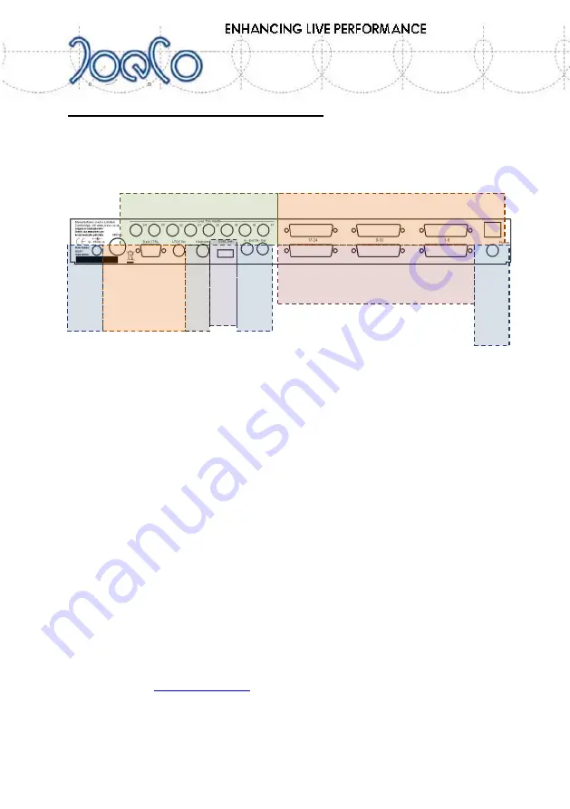
Rear Panel of 24 channel BlackBox
The rear panel will look slightly different depending on which style of audio
interface you have on your BlackBox Player. The areas indicated in the
diagram below are explained in more detail later in this manual.
The lower 3 D-type connectors are the main Unbalanced Analogue i/o
connectors on the BBP1U, BBP1A and BBP1D. The cable looms conform to
the TASCAM standard for analogue i/o.
On the BBP1B with Balanced i/o, these lower 3 D-type connectors are the
balanced inputs and the upper row are the balanced outputs. The BBP1B
does not have the loop through inserts, as the output cables can be plugged
into any external effects required before returning to the console.
On the BBP1A (Lightpipe i/o) version, the upper option area contains the
Lightpipe i/o connections and the lower row of D-types are unbalanced
analogue i/o.
On the BBP1D (AES/EBU i/o) version, the upper row of D-type connectors
provide digital i/o (normally configured to the Yamaha standard pin out) and
the lower row of D-types are unbalanced analogue i/o.
The rest of the rear panel is fairly self-explanatory, we hope, and is explained
in greater detail later in this manual. There are more technical details on the
JoeCo website (
www.joeco.co.uk
) should you require them. Please use the
Log In button and register your interest to download more information.
i/o options
Loop through insert points
Unbalanced Analogue i/o
Clo
cks
Di
sk
Ke
yb
o
ard
H
ead
p
h
o
n
e
s
Sync and
Control
Po
w
er


