background image


17 


DRIVING SCREWS 

– cont’d 

 
1.  Select the correct screwdriver bit for 

the screw being driven. 
 

2.  Fasten the screwdriver bit into the 

chuck, making sure the flats of the bit 
are gripped by the chuck jaws. 
 

3.  Set the torque clutch to the appropriate 

setting based on the chart shown on 
Page 13. 

NOTE:

 If material is particularly soft or 

porous, set the torque clutch at a lower 
setting to avoid overdriving the screw. 


4.  If the screw is driven too far into the 

workpiece before the clutch releases, 
set the clutch to a lower setting and do 
not pull the trigger switch fully back. If 
the screw is not driven far enough into 
the workpiece, set the clutch at a 
higher setting. 

NOTE:

 Do not continue to drive the 

screw once the clutch has released. 
This will damage the clutch. 
 

CHUCK REMOVAL 

 
To remove the chuck: 
 
1.  Remove the battery pack from the drill. 


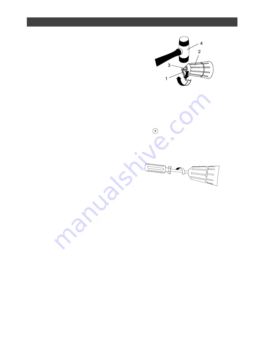
2. 

Insert a 5/16” or larger hex key (1) into 
the chuck (2) and tighten the chuck 
jaws securely. Make sure each of the 
chuck jaws (3) is seated on the flat 
surfaces of the hex key (Fig. 12). 
 

3.  Tap the hex key sharply with a mallet 

(4) in a clockwise direction.  This action 
will loosen the screw in the chuck for 
easy removal. 


4.  Open chuck jaws and remove hex key. 


5.  Open chuck jaws as far as possible. 


6.  Remove the chuck screw using a  

#2        screwdriver (see Fig. 13).   

NOTE:

 Turn screw CLOCKWISE to 

remove it. This screw has a left-
handed thread.


7.  Insert the hex key into the chuck and 

tighten jaws of chuck securely  
(Fig. 14).  Tap the hex key sharply with 
a mallet in a COUNTER-CLOCKWISE 
direction. This will loosen the chuck on 
the spindle. The chuck can now be 
unscrewed and removed from the 
spindle by hand.


ASSEMBLY & OPERATION 

Fig. 12 


Fig. 13 


Summary of Contents for 54-2902-4

Page 1: ...of its accessories read this manual and follow all Safety Rules and Operating Instructions General Safety Rules Specific Safety Rules and Symbols Functional Description Assembly Operation Maintenance...

Page 2: ...t carries a one 1 year warranty against defects in workmanship and materials Trileaf Distribution agrees to replace the defective product free of charge with the same model or one of equal value or sp...

Page 3: ...s wired at the factory for 110 120 V operation It must be connected to a 110 120 V 15 A time delayed fuse or circuit breaker To avoid shock or fire replace power cord immediately if it is worn cut or...

Page 4: ...will increase the risk of electric shock Do not abuse the cord Never use the cord to carry the tools or pull the plug from an outlet Keep cord away from heat oil sharp edges or moving parts Replace da...

Page 5: ...ignment or binding of moving parts breakage of parts and any other condition that may affect the tool s operation If damaged have the tool serviced before using Many accidents are caused by poorly mai...

Page 6: ...Always make sure the chuck is tight and the drill bit firmly tightened in the chuck before starting drill Do not store or carry battery in a manner in which metal objects could contact the exposed met...

Page 7: ...perate charger if cord or plug is damaged Replace damaged cord and plug immediately Do not operate charger if it has received a sharp blow been dropped or otherwise damaged in any way Have a qualified...

Page 8: ...rotective earthing at earthing terminal Class I tools revolutions or reciprocations per minute diameter off position arrow warning symbol recycle Ni Cd nickel cadmium battery do not throw in garbage d...

Page 9: ...ESS DRILL wo speed gearbox Charger stand Battery charger 3 8 Keyless chuck Clutch Forward reverse switch On board screwdriver bit storage 18 V Battery pack Carry strap Trigger switch Spirit level Spee...

Page 10: ...nner or similar highly volatile solvents to clean the tool CARTON CONTENTS DRILL COMPONENTS KEY DESCRIPTION QTY A Drill 1 B Double ended screwdriver bits 1 2 2 6 mm 1 1 C 18 V Battery pack 1 D Masonry...

Page 11: ...11 CARTON CONTENTS...

Page 12: ...that is completely run down should be charged for 5 hours After normal use a battery pack should be fully charged in about 3 hours b It is normal for the battery charger to hum and be warm to the tou...

Page 13: ...driving screws into hardwood 15 For driving large screws Use highest setting for drilling This position is marked with a picture of a drill bit on the torque adjustment ring FORWARD REVERSE SWITCH Th...

Page 14: ...ool for at least 15 minutes INSTALLING DRILL BITS WARNING Never hold the chuck body with one hand and use the drill power to rotate the drill body to loosen or tighten bits Serious injury may result 1...

Page 15: ...r and rotate the chuck body in a counter clockwise direction until the chuck jaws open and release the bit 2 Remove the drill bit LEVELING THE DRILL The drill is equipped with a horizontal level to as...

Page 16: ...speed when drilling small holes Use a slower drill speed when drilling large holes 5 Move the drill bit into the workpiece applying only enough pressure to keep the bit cutting Do not force the drill...

Page 17: ...leased This will damage the clutch CHUCK REMOVAL To remove the chuck 1 Remove the battery pack from the drill 2 Insert a 5 16 or larger hex key 1 into the chuck 2 and tighten the chuck jaws securely M...

Page 18: ...use solvents when cleaning plastic parts Most plastics are susceptible to damage from various types of commercial solvents and may be damaged by their use Use clean cloth to remove dirt dust oil greas...

Page 19: ...or power long operational life and light weight your tool is powered by a Nickel cadmium battery pack Nickel cadmium batteries are powerful rugged and will provide hundreds of charge discharge cycles...

Page 20: ...with and work with the tool until it nearly stops and no longer produces useful action 2 If the tool came in a kit with a worklight insert the battery into the light Turn the switch ON and leave it O...

Page 21: ...21 PARTS DIAGRAM MODEL 54 2902 4 Cordless Drill...

Page 22: ...screw ST2 9x20 1 4 654819 Battery pack 1 5 315821 Inner threaded ring 1 6 203046 Toque adjusting ring 1 7 242503 Positioning spring 1 8 152502 Compressing plate 1 9 500005 Tapping screw 2 10 161117 Ch...

Page 23: ...11 Fixed gear ring 1 38 221228 Washer 1 39 500801 Self tapping screw M3x8 2 40 316504 Motor flange 1 41 200022 Motor gear 1 42 130014 Motor 1 43 306106 Left enclosure 1 44 164204 Cylindrical spirit le...

Reviews: