background image

14

4:5

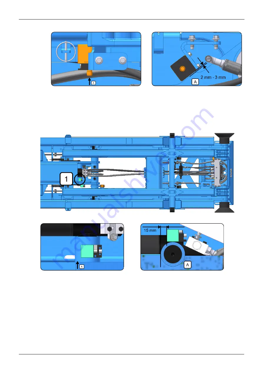
Inspect the ultra sonic sensor for the extending-section, where applicable. Make sure
that it is positioned correctly and free from damage.

NOTE:

This is optional equipment. It is not standard.

4:6

Verify that the ultra-sonic sensor functions correctly and that it stops the extending-sec-
tion. To do this, follow the procedure below:

1. Operate the hook-lift and tip it up, in tip mode.

2. Operate the extending section and fully retract it (move it inwards). The ultra-

sonic sensor should detect the extending section moving towards it and even-
tually signal for the extending-section to be stopped, approximately 300 mm
from its end point. This ensures that the centre-lock is not activated.

Service Instruction: EcoDrive | 13301 Edition 1b | 2019-02-31

Group 4 – Inspection and Adjustment

Summary of Contents for EcoDrive Hook-Lift L

Page 1: ...Base Service Hook Lifts www joab se 13301 Edition 1b 2019 02 31 KM JOAB Försäljnings AB Östergärde Industriområde 417 29 Göteborg Telephone 031 705 06 00 Telefax 031 705 06 09 E post info joab se ...

Page 2: ...ii Service Instruction EcoDrive 13301 Edition 1b 2019 02 31 ...

Page 3: ...nts 3 Group 2 Torque the Chassis Brackets 5 Group 3 Operation and Function Check 7 Group 4 Inspection and Adjustment 11 Group 5 Lubrication 27 Safety Warnings 29 Appendix 1 CBW Control Stick 31 Main Functions 31 Snow Plough Functions 32 Appendix 2 CBW User Interface 33 Icon Definitions 33 Emergency Operation 35 Contact Information 37 Service Packets and Warranty 37 ...

Page 4: ...iv Service Instruction EcoDrive 13301 Edition 1b 2019 02 31 Table of Contents ...

Page 5: ...ls The specifications constructions and illustrations found in this service procedure are not bind ing JOAB AB retains the right to make changes without prior notice Before performing a service on a EcoDrive Hook Lift make sure that you have read and are fully aware of all safety warnings in the EcoDrive s operator manual Failure to do so can lead to serious injury or damage to equipment Always ba...

Page 6: ...vi Service Instruction EcoDrive 13301 Edition 1b 2019 02 31 Introduction ...

Page 7: ...t A Sub frame B Auxiliary lifting arm C Inner rear section D Intermediate section E Extending section F Hook G Hook post H Hydraulic lock I Folding hook post LA models only J Safety hook LA models only K Centre lock L Spreader flap deployer accessory M Rollers Required Equipment The following table lists the materials required to carry out the base service Service Instruction EcoDrive 13301 Editio...

Page 8: ...t taken Make sure that all personnel are competent and aware of the risks before working on the hook lift Before starting work with the hook lift read and adhere to the safety warnings provided under Safety Warnings on page 29 Failure to adhere to the safety warnings can lead to serious injury or damage to equipment In addition read and adhere to all safety warnings provided in the vehicle s docum...

Page 9: ...tems with new ones 1 The air filter 2 The hydraulic filter 3 The O ring for the hydraulic filter 1 2 Clean the area around the hydraulic tank s drain plug 1 Unscrew the plug and com pletely drain the oil Then replace the drain plug and refill the tank with new oil Refer to Required Equipment on page 1 for details of the correct oil to use Service Instruction EcoDrive 13301 Edition 1b 2019 02 31 ...

Page 10: ...4 Service Instruction EcoDrive 13301 Edition 1b 2019 02 31 Group 1 Replace Service Components ...

Page 11: ...uing of the bolts 2 2 Check all of the chassis s fastening brackets and make sure that all bolts are correctly torqued Use the toque settings listed below in Table 2 for all bolts except head bolts For head bolts use a torque value of 40 Nm Thread Metric Class 8 8 Class 10 9 M14 128 Nm 181 Nm M16 197 Nm 277 Nm Table 2 Torque setting for chassis brackets Provide below are some examples of the chass...

Page 12: ...6 Service Instruction EcoDrive 13301 Edition 1b 2019 02 31 Group 2 Torque the Chassis Brackets ...

Page 13: ...hook lift is not in drive status It is not fully retracted The center lock is open The hydraulic lock is open The safety hook is open LA models only Table 3 User interface warnings 5 Check that the emergency stop button functions correctly Turn the pump for the hook lift ON operate the hook lift and then activate the emergency stop to verify that it stops the hook lift from working Reset the emerg...

Page 14: ...rectly Refer to Snow Plough Functions on page 32 for information regarding operation of the CBW controller s control stick for snow plough functions When operating the optional functions under load listen to the vehicle s engine and hydraulic pump and verify that all functions correctly Look for hydraulic leaks and listen for unusual noises 3 6 Operate the emergency override system for the hook li...

Page 15: ...IN 8 Hydraulic lock OPEN Extra 6 Side Plough OUT 9 Spreader flap Start motor Extra 7 10 Automatic flap Stop motor Extra 8 11 Safety hook LA models 12 Change function mode Change function mode Change function mode Table 4 Radio controller functions 3 8 Operate and make sure that any buttons and lights that are in addition to the CBW con troller function correctly NOTE Some vehicle s may be equipped...

Page 16: ...s shown below NOTE This is optional equipment 3 10 Operate all external lights on the hook lift and make sure that they function correctly including the reverse lights 3 11 Turn the hook lift s work lights on and verify that they all function correctly Service Instruction EcoDrive 13301 Edition 1b 2019 02 31 Group 3 Operation and Function Check ...

Page 17: ...BW controller refer to Appendix 1 CBW Control Stick on page 31 1 Retract the extending section fully 2 Tip the hook up in Shunting mode 3 Extend the extending section fully 4 Lower the Hook Lift fully 5 Lock the hydraulic lock 6 Tip the hook in tip mode 4 2 With the hook lift in the tipped state as shown above 6 inspect and verify that the centre lock on both sides of the hook lift is fully engage...

Page 18: ...andard sensors as shown and described below to verify that they are not damaged and are correctly positioned 1 Verify that the sensor for the intermediate section is free from damage See also the location numbered 1 above Measure the tolerance as shown below and adjust as required so that the sensor is positioned correctly with a tolerance of 3 2 mm 2 Inspect and verify that the sensor for the cen...

Page 19: ... damage See also location numbered 3 above Measure the tolerance as shown below and adjust as required so that the sensor is positioned cor rectly with a tolerance of 2 mm 3 mm 4 Inspect the two sensors for the hydraulic lock as shown below one on each side Make sure that they are correctly adjusted and free from damage Refer also to the locations numbered 4 above 5 Inspect the sensor for tipping ...

Page 20: ...sec tion To do this follow the procedure below 1 Operate the hook lift and tip it up in tip mode 2 Operate the extending section and fully retract it move it inwards The ultra sonic sensor should detect the extending section moving towards it and even tually signal for the extending section to be stopped approximately 300 mm from its end point This ensures that the centre lock is not activated Ser...

Page 21: ...y hook 1 Operate the hook lift and engage the hook with a lifting bracket on a body Then operate the safety hook Verify that it functions correctly and fastens the hook onto the lifting bracket Check that the safety hook moves freely and smoothly and that it does not leak air 2 Verify that the folding hook post and its over centre valves OC function cor rectly Operate the folding hook post in each...

Page 22: ...play in the hook post as shown below The play must be less than 10 mm when moved from side to side as shown below 4 11 Raise the auxiliary arms and inspect them as follows 1 Verify that the cylinders that carry the body are free to rotate Make sure that they rotate smoothly and without resistance Service Instruction EcoDrive 13301 Edition 1b 2019 02 31 Group 4 Inspection and Adjustment ...

Page 23: ...s 5 Inspect the fastening points for wear or damage 4 12 Inspect the shunting axle components as follows 1 Inspect the housings for the shunting axle on the sub frame Check for damage or wear 2 Inspect the locking arms for the shunting axle as shown above Check for dam age and wear 3 Inspect the lock pins for the shunting axle Make sure that the circlips are cor rectly positioned and there is no d...

Page 24: ... 2 Leave the hook post in position and observe it Observe to see whether or not the extending section or the hook post moves If either of them moves their is a leak in the respective OC valves If the OC valves leak they must be fixed 4 15 Inspect all the glide lugs on the hook lift s frame for damage and wear as shown below If necessary remove any sharp edges to prevent them from causing damage to...

Page 25: ... for free play on the locking claws 4 Check for hydraulic fluid leaks 4 17 Verify that the spreader flap deployer functions correctly as follows NOTE This is optional equipment It is not standard 1 Operate the spreader flap and verify that it functions correctly Make sure it moves freely and without any resistance 2 Release the spreader flap and verify that it returns to its parked position fully ...

Page 26: ...and excessive free play 2 Make sure that the grease points for the bearings are free from damage 3 Inspect the tip axle for material damage 4 19 Verify that the rollers on the back of the hook lift move freely and that the bearings do not have play in them Service Instruction EcoDrive 13301 Edition 1b 2019 02 31 Group 4 Inspection and Adjustment ...

Page 27: ...the plastic protective cover from the main valve block to gain access to it and its peripheral devices as shown above 3 Check the valve block and its connections for oil leaks and damage Make sure that all hydraulic connections are correctly connected and do not leak 4 22 Inspect the high pressure filter s container as shown in the above image Make sure there are no leaks and that all connections ...

Page 28: ...raulic connections are correctly connected and do not leak 2 Inspect the connections Make sure they are routed and connected properly If there are any signs of corrosion or damage make sure these are fully invest igated and corrected 3 Inspect the I O module s for all extra equipment Make sure that all connections are correctly connected and there is no sign of damage If there is any sign of damag...

Page 29: ...wn above Make sure all connections are routed and connected properly If there are any signs of cor rosion or damage make sure these are fully investigated and corrected 4 27 Inspect the following items for damage Make sure that all connections are correctly tightened and do not leak 1 The EcoDrive Load holding valve block ELH 2 The Fast Drive System Plus FDS and Fast Lowering System Plus FLS valve...

Page 30: ...c hoses pipes and connections for the hook lift s entire hydraulic system Check for cracks and any other signs of damage Make adjustments as neces sary to ensure that there is no risk of damage to the pipes and hoses due to poor rout ing of them 4 31 Check all valves for the hook lift and make sure that they function correctly and that they do not leak 4 32 Inspect the hook lift s external mounted...

Page 31: ...d function correctly 4 33 Check and make sure that all electrical wiring for the hook lift is free from damage or deterioration Inspect the following 1 Check the wiring harnesses for damage Make sure that they are correctly secured and routed Make adjustments as necessary 2 Check all cables and their contacts for damage Make sure that the cables are properly attached to there contact points If it ...

Page 32: ...26 Service Instruction EcoDrive 13301 Edition 1b 2019 02 31 Group 4 Inspection and Adjustment ...

Page 33: ... cylinder x 4 2 Auxiliary lift arm x 4 l 3 Auxiliary lift cylinder x 4 4 Centre lock 5 Extending section cylinder x 2 6 Shunting pivot x2 7 Rollers x 2 8 Tip pivot x 2 9 Hydraulic lock cylinder x 2 Hook Lift LA optional 10 Hook post cylinder X 2 11 Hook post axle X 2 Service Instruction EcoDrive 13301 Edition 1b 2019 02 31 ...

Page 34: ...28 Service Instruction EcoDrive 13301 Edition 1b 2019 02 31 Group 5 Lubrication ...

Page 35: ...at the tip supports are mounted correctly so that they support the hook lift before carrying out any work Park the Hook Lift before driving the Vehicle Make sure the hook lift is parked before driving the vehicle Failure to do so can lead to serious injury or damage There is a serious risk that the hook will make contact with the envir onment if it is not parked Risk of Slipping Be aware when oper...

Page 36: ...efore using the emergency operation function check and verify if the hook lift is equipped with extended tip cylinders It is the responsibility of the operator to make sure that they are aware of which safety precautions apply Failure to do so can lead to serious injury or damage to the equipment and environment Service Instruction EcoDrive 13301 Edition 1b 2019 02 31 Safety Warnings ...

Page 37: ...ull backwards Bottom button pressed and pull backwards Turn the knob ant clockwise Tip Down Tip Down Fast Operation Extending Section OUT Push forwards Bottom button pressed and push forwards Turn the knob clockwise Folding Hook Post UP Folding Hook Post DOWN Auto Cycle Load Push the knob to the right Push the knob to the left Top button pressed and push forwards Table 5 CBW controller stick funct...

Page 38: ...inued Extra option LA models only Snow Plough Functions Side plough UP Side plough OUT Front plough LEFT Bottom button pressed Push the knob right Turn the knob ant clockwise Side plough DOWN Front plough UP Front plough RIGHT Top button pressed Pull the knob backwards Turn the knob clockwise Side plough IN Front plough DOWN Push the knob left Push the knob forwards Table 6 CBW controller stick sn...

Page 39: ...ivated for all installations Some of the functions are optional extras these are marked with an asterisk Functions that can be selected for the programmable areas F1 F4 and the UP and DOWN buttons are coloured white All other buttons orange and green simply provide feedback to the user as to whether or not they are active Icon Function Icon Function Night mode Deactivate FFD2 Read NOTE 2 below Loa...

Page 40: ...wered status Axle lift TRAILER Automatic flap VEHICLE Position memory system Table 7 User interface icon description continued NOTE 1 The above functions Automatic flap VEHICLE and Automatic flap TRAILER can be operated without the hydraulic pump being turned ON Simply keep the icon pressed for 10 seconds to activate them without turning the pump on NOTE2 FFD must be activated when working with bo...

Page 41: ... in the hook lift s system it is possible to still operate the hook lift using the emer gency system To activate the emergency system fol low the procedure listed below If in any doubt about the use of the emergency over ride contact JOAB for advice before using it 1 Turn the hydraulic pump on 2 Press and hold down the OK button for five seconds to open the Diagnostics and Statistics page as shown...

Page 42: ...36 Service Instruction EcoDrive 13301 Edition 1b 2019 02 31 Appendix 2 CBW User Interface ...

Page 43: ...fore making con tact Department Contact Details Service and Spare Parts JOAB Göteborg telephone 46 31 7050600 Warranty JOAB Göteborg telephone 46 31 7050600 Spare Parts JOAB Göteborg telephone 46 31 7050610 46 31 7050612 46 31 7050686 Technical Support JOAB Göteborg telephone 46 31 7050620 46 31 7050688 Service JOAB Göteborg telephone 46 31 7050621 46 31 7050687 Service JOAB Dals Rostock telephone...

Page 44: ...AB Täby Stockholm North telephone 46 873 25875 Service JOAB Täby Stockholm North telephone 46 863 08871 Table 8 Service packets continued Visit our website www joab se to order spare parts and find your nearest JOAB authorised workshop Service Instruction EcoDrive 13301 Edition 1b 2019 02 31 Contact Information ...

Page 45: ...39 Service Instruction EcoDrive 13301 Edition 1b 2019 02 31 Contact Information ...

Reviews: