


SECTION 2 - PROCEDURES
3120863
– JLG Lift –
2-11
2.9
CYLINDER REPAIR
NOTE:
The following are general procedures that apply to
all of the cylinders on this machine. Procedures that
apply to a specific cylinder will be so noted.
NOTE:
See Figure 2-5., Figure 2-6., Figure 2-7., and Figure
2-8. for the breakdown of typical hydraulic cylinders
used on this machine.
Disassembly
DISASSEMBLY OF THE CYLINDER SHOULD BE PERFORMED ON
A CLEAN WORK SURFACE IN A DIRT FREE WORK AREA.
1.
Connect a suitable auxiliary hydraulic power source
to the cylinder port block fitting.
DO NOT FULLY EXTEND THE CYLINDER TO THE END OF THE
STROKE. RETRACT THE CYLINDER SLIGHTLY TO AVOID TRAP-
PING PRESSURE.
2.
Operate the hydraulic power source and extend the
cylinder. Shut down and disconnect the power
source. Adequately support the cylinder rod, if appli-
cable.
ON CYLINDERS WITH DOUBLE HOLDING VALVES, BEFORE
REMOVING HOLDING VALVES, CRACK THE BLEEDERS TO
RELEASE PRESSURE.
3.
If applicable, remove the cartridge-type holding
valve and fittings from the cylinder port block. Dis-
card the o-rings.
NOTE:
Step 4 applies only to the Telescope Cylinder.
4.
Remove the nuts which attach each cylinder rod
support block pull rod and withdraw the rods from
the forward end of the telescope cylinder.
5.
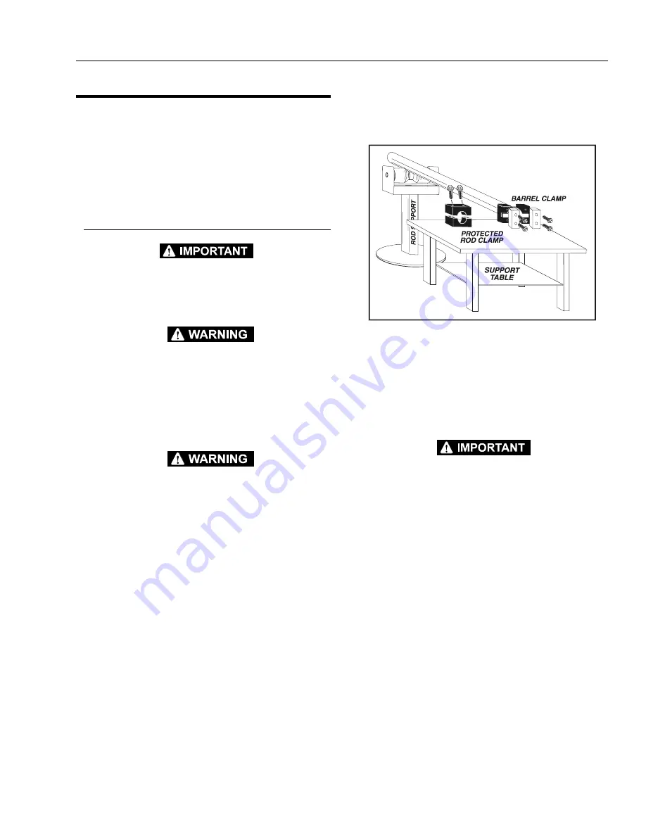
Place the cylinder barrel into a suitable holding fix-
ture. Tap around the outside of the cylinder head
retainer with a suitable hammer to shatter the loctite
seal.
6.
Using a suitable spanner wrench, loosen the cylin-
der head retainer, if applicable, and/or cylinder head
gland, and remove from cylinder barrel.
7.
Attach a suitable pulling device to the cylinder rod
port block end or cylinder rod end, as applicable.
EXTREME CARE SHOULD BE TAKEN WHEN REMOVING THE CYL-
INDER ROD, HEAD, AND PISTON. AVOID PULLING THE ROD OFF-
CENTER, WHICH COULD CAUSE DAMAGE TO THE PISTON AND
CYLINDER BARREL SURFACES.
8.
With the barrel clamped securely, apply pressure to
the rod pulling device and carefully withdraw the
complete rod assembly from the cylinder barrel.
Figure 2-4. Cylinder Barrel Support
Summary of Contents for 80HX
Page 2: ......
Page 10: ...vi JLG Lift 3120863 TABLE OF CONTENTS Continued THIS PAGE LEFT BLANK INTENTIONALLY...
Page 16: ...SECTION 1 SPECIFICATIONS 1 6 JLG Lift 3120863 Figure 1 2 Lubrication Diagram...
Page 27: ...SECTION 2 PROCEDURES 3120863 JLG Lift 2 5 Figure 2 1 Proportional Control Valve...
Page 34: ...SECTION 2 PROCEDURES 2 12 JLG Lift 3120863 Figure 2 5 Typical Hydraulic Cylinders Sheet 1 of 4...
Page 35: ...SECTION 2 PROCEDURES 3120863 JLG Lift 2 13 Figure 2 6 Typical Hydraulic Cylinders Sheet 2 of 4...
Page 36: ...SECTION 2 PROCEDURES 2 14 JLG Lift 3120863 Figure 2 7 Typical Hydraulic Cylinders Sheet 3 of 4...
Page 37: ...SECTION 2 PROCEDURES 3120863 JLG Lift 2 15 Figure 2 8 Typical Hydraulic Cylinders Sheet 4 of 4...
Page 44: ...SECTION 2 PROCEDURES 2 22 JLG Lift 3120863 Figure 2 12 Boom Assembly Sheet 1 of 2...
Page 45: ...SECTION 2 PROCEDURES 3120863 JLG Lift 2 23 Figure 2 13 Boom Assembly Sheet 2 of 2...
Page 53: ...SECTION 2 PROCEDURES 3120863 JLG Lift 2 31 Figure 2 16 Adeco Actuator Adjustments F4L912...
Page 68: ...SECTION 2 PROCEDURES 2 46 JLG Lift 3120863 Figure 2 32 Swing Bearing Torquing Sequence...
Page 70: ...SECTION 2 PROCEDURES 2 48 JLG Lift 3120863 Figure 2 33 Torque Hub Assembly...
Page 108: ...SECTION 3 TROUBLESHOOTING 3 20 JLG Lift 3120863 Figure 3 1 Wiring Schematic Sheet 1 of 4...
Page 110: ...SECTION 3 TROUBLESHOOTING 3 22 JLG Lift 3120863 Figure 3 3 Wiring Schematic Sheet 3 of 4...
Page 112: ...SECTION 3 TROUBLESHOOTING 3 24 JLG Lift 3120863 Figure 3 5 Hydraulic Schematic Sheet 1 of 6...
Page 114: ...SECTION 3 TROUBLESHOOTING 3 26 JLG Lift 3120863 Figure 3 7 Hydraulic Schematic Sheet 3 of 6...
Page 116: ...SECTION 3 TROUBLESHOOTING 3 28 JLG Lift 3120863 Figure 3 9 Hydraulic Schematic Sheet 5 of 6...
Page 118: ...SECTION 3 TROUBLESHOOTING 3 30 JLG Lift 3120863 This page left blank intentionally...
Page 119: ......


