
SECTION 4 - MACHINE OPERATION
3120889
– JLG Lift –
4-1
SECTION 4. MACHINE OPERATION
4.1
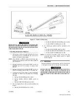
DESCRIPTION
This machine is a self-propelled aerial work platform on
the end of an elevating, telescoping and rotating boom.
The JLG Lift’s intended purpose is to position personnel
with their tools and supplies at positions above ground
level. The machine can be used to reach work areas
located above and over machinery or equipment.
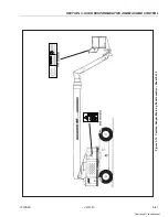
The JLG Lift has a primary operator Control Station in the
platform. From this Control Station, the operator can drive
and steer the machine in both forward and reverse direc-
tions. The operator can raise, lower, extend or retract the
boom; swing the boom to the left or rig ht; and when
equipped with a platform rotator, can rotate the platform
around the boom end. Standard boom swing is 360° con-
tinuous left and right of the stowed position. The machine
has a Ground Control Station which will override the Plat-
form Control Station. Ground Controls operate boom lift,
telescope and swing and are to be used only in an emer-
gency to lower the platform to the ground should the
operator in the platform be unable to do so.
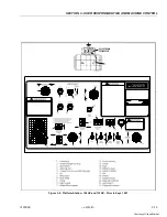
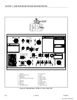
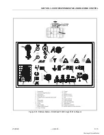
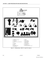
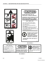
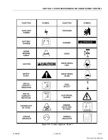
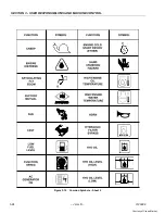
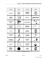
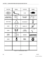
Instruction and hazard warnings are posted adjacent to
both operator control stations and at other places on the
machine. It is extremely important that operators know
wh at in struc tio n s and w arnin g s are p lac ed o n th e
machine, and review these periodically so that they are
fresh in their minds.
The JLG Lift is designed to provide efficient and safe oper-
ation when maintained and operated in accordance with
warnings on the machine, in the Operators and Safety
Manual, and all jobsite and government rules and regula-
tions. As with any type of machinery, the operator is very
important to efficient and safe operation. It is absolutely
necessary that the JLG Lift be regularly maintained in
accordance with this manual and the machine Service
and Maintenance manual, and that any evidence of lack of
maintenance, malfunction, excessive wear, damage or
modification to the machine be reported immediately to
the machine owner or the jobsite supervisor or safety
manager and that the machine be taken out of service
until all discrepancies are corrected.
The JLG Lift is not intended to be used to lift material other
than supplies which personnel in the platform require to
do their job. Supplies or tools which extend outside the
platform are prohibited. It must not be used as a forklift,
crane, support for overhead structure, or to push or pull
another object or the lift itself.
The machine is equipped with an auxiliary battery oper-
ated power unit which will provide hydraulic power in the
event of a primary engine power loss. Auxiliary power can
be controlled from either the Platform Control Station or
the Ground Control Station. Follow the instructions placed
at the control stations.
The JLG Lift is hydraulically powered using hydraulic
motors and cylinders for various machine motions. The
hydraulic components are controlled by electrically acti-
vated hydraulic valves using switches and control levers.
The speeds of functions controlled by control levers are
variable from zero to maximum speed depending upon
the position of the control lever. Functions controlled by
toggle switches are either on or off and higher or lower
speed is possible when the Function Speed control switch
is used in conjunction with the function toggle switch. A
foot operated switch in the platform must be depressed
before any controls will function and provides a means of
emergency stop when the operator’s foot is removed from
the footswitch.
The JLG Lift is a two wheel drive machine with drive power
being supplied by a hydraulic motor for each drive wheel.
Each drive wheel is supplied with a hydraulically released,
spring-applied brake. The swing drive is also equipped
with such a brake. These brakes are automatically applied
any time the Drive or Swing Control lever are returned to
the neutral position.
Refer to the capacity decal in the platform and at the
ground control station for the rated capacity. See instruc-
tions in this manual and on the machine for checking pro-
cedures.
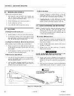
4.2
GENERAL
This section provides the necessary information needed
to operate the machine. Included in this section are the
procedures for starting, stopping, traveling, steering, park-
ing, platform loading and transporting. It is important that
the user read and understand the proper procedures
before operating the machine.
Summary of Contents for 100HX
Page 2: ...Courtesy of Crane Market...
Page 4: ...FOREWORD b JLG Lift 3120889 This page left blank intentionally Courtesy of Crane Market...
Page 6: ...FOREWORD d JLG Lift 3120889 REVISON LOG January 1999 Original Issue Courtesy of Crane Market...
Page 78: ...Courtesy of Crane Market...
Page 79: ...Courtesy of Crane Market...


