background image

13

D.  FRESH AIR SUPPLY REQUIREMENTS

When the dryer is operating, it draws in room air, heats it, passes this air through the basket (tumbler), and
exhausts it out of the building.  Therefore, the room air 

must be

 continually replenished from the outdoors.  If the

make-up air is inadequate, drying time and drying efficiency will be adversely affected.  Ignition problems and
sail switch “fluttering” problems may result, as well as premature motor failure from overheating.

Air supply (make-up air) 

must be

 given careful consideration to assure proper performance of each dryer.  An

unrestricted source of air is necessary for each dryer.  An airflow of 1,200 cfm (cubic feet per minute) (33.98
cmm [cubic meters per minute]) 

must be

 supplied to each gas dryer.  As a general rule, an unrestricted air

entrance from the outdoors (atmosphere) of a minimum of 1-1/2 square feet (0.41 square meters) is required for
each dryer.  The dryer 

must be

 installed with provisions for adequate combustion and make-up air supply.

To compensate for the use of registers or louvers used over the openings, this make-up air 

must be 

increased by

approximately thirty-three percent (33%).  Make-up air openings 

should not be

 located in an area directly near

where exhaust vents exit the building.

It is not necessary to have separate make-up air openings for each dryer.  Common make-up air openings are
acceptable.  However, they 

must be

 set up in such a manner that the make-up air is distributed equally to 

ALL

the dryers.

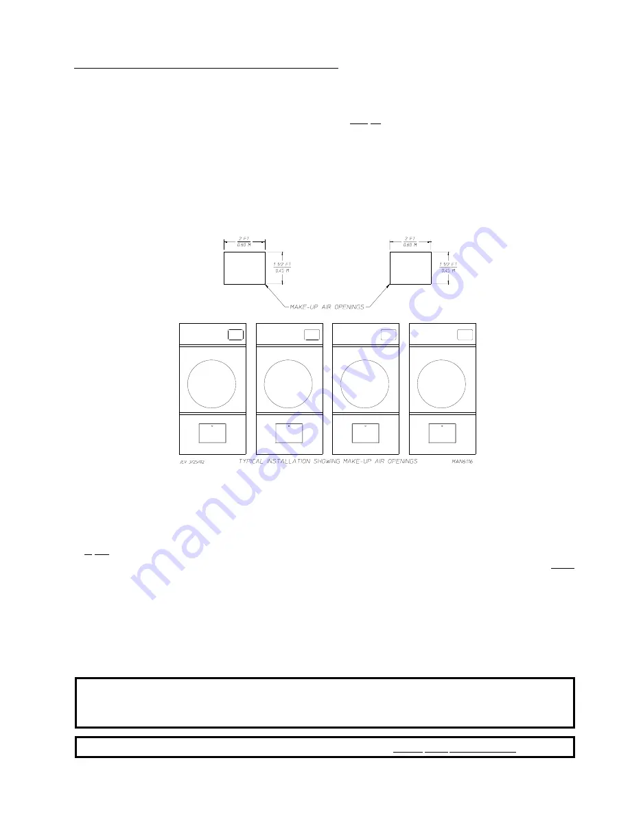
EXAMPLE:

For a bank of four (4) dryers, two (2) unrestricted openings measuring 2 feet x 1-1/2 feet (0.60 meters
x 0.45 meters) (6 square feet [0.56 square meters]) are acceptable.

Allowances 

must be

 made for remote or constricting passageways or where dryers are located at excessive

altitudes or predominantly low pressure areas.

IMPORTANT:

Make-up air 

must be

 provided from a source free of dry cleaning solvent fumes.

Make-up air that is contaminated by dry cleaning solvent fumes will result in
irreparable damage to the motors and other dryer components.

NOTE:

Component failure due to dry cleaning solvent fumes will VOID THE WARRANTY.

Summary of Contents for D-78

Page 1: ...he gas supplier AVERTISSEMENT Assurez vous de bien suivrelesinstructionsdonnéesdanscettenotice pour réduire au minimum le risque d incendie ou d explosion ou pour éviter tout dommage matériel touteblessureoulamort Ne pas entreposer ni utiliser d essence ni d autres vapeurs ou liquides inflammables à proximité de cet appareil ou de tout autre appareil QUEFAIRESIVOUSSENTEZUNEODEUR DEGAZ Ne pas tente...

Page 2: ...______________________________________________________ Serial Number s ________________________________________________________________________________________ ________________________________________________________________________________________ ________________________________________________________________________________________ Replacement parts can be obtained from your distributor or JLA...

Page 3: ...YERSINOPERATION DRYERSSHOULDNEVERBELEFTUNATTENDEDWHILEINOPERATION CAUTION FOR YOUR SAFETY DONOTDRYMOPHEADSINTHEDRYER DONOTUSEDRYERINTHEPRESENCEOFDRYCLEANINGFUMES WARNING UNDER NO CIRCUMSTANCES should the dryer door switches lint drawer switch or heat safety circuit ever be disabled Caution Label ALL wires prior to disconnection when servicing controls Wiring errors can cause improper operation Att...

Page 4: ...displayedontheequipmentand or specified in the installation manual included with the dryer WARNING DRYER MUST NEVER BE OPERATEDWITHOUTTHE LINTFILTER SCREEN IN PLACE EVENIFANEXTERNALLINTCOLLECTIONSYSTEMISUSED Dryer must not be installed or stored in an area where it will be exposed to water or weather The wiring diagram for the dryer is located in the front electrical control box area ...

Page 5: ...ureRequirements 12 D FreshAirSupplyRequirements 13 E ExhaustRequirements 14 F ElectricalInformation 18 G GasInformation 24 H Preparation for Operation Start Up 28 I PreoperationalTests 29 J PreoperationalInstructions 31 K ShutDownInstructions 32 SECTION IV SERVICE PARTS INFORMATION 33 A Service 33 B Parts 33 SECTION V WARRANTY INFORMATION 34 A ReturningWarrantyCards 34 B Warranty 34 SECTION VI ROU...

Page 6: ...peration 44 SystemReset 44 OPLS A F E System Check Procedure 44 SensorActivatedFireExtinguishing S A F E SystemPartsBreakDown 45 SECTION X COIN SENSOR ACTIVATED FIRE EXTINGUISHING S A F E SYSTEM 47 Installation 48 SensorActivatedFireExtinguishing S A F E SystemTheoryofOperation 51 DisabledSensorActivatedFireExtinguishing S A F E System 51 S A F E Diagnostic Messages 51 SystemReset 51 SensorActivat...

Page 7: ...cepted but the number received and the number refused must be noted on the receipt 4 If you determine that the dryer was damaged after the trucker has left your location you should call the delivering carrier s freight terminal immediately and file a claim The freight company considers this concealed damage This type of freight claim is very difficult to get paid and becomes extremely difficult wh...

Page 8: ...our gas supplier from a neighbor s phone Follow the gas supplier s instructions f If you cannot reach your gas supplier call the fire department 4 Installation and service must be performed by a qualified installer service agency or gas supplier 5 Dryers must be exhausted to the outdoors 6 Although the manufacturer produces a very versatile dryer there are some articles that due to fabric composit...

Page 9: ...or switches lint drawer switch or heat safety circuit ever be disabled WARNING PERSONALINJURYOR FIRE COULD RESULT 10 This dryer is not to be used in the presence of dry cleaning solvents or fumes 11 Remove articles from the dryer as soon as the drying cycle has been completed WARNING Articlesleftinthedryerafterthedryingandcoolingcycleshavebeencompletedcan create a fire hazard 12 READ AND FOLLOW AL...

Page 10: ...7 8 63 2 cm BASKET TUMBLER MOTOR 1 HP 0 746 kw DOOR OPENING DIAMETER 31 3 8 79 7 cm BASKET TUMBLER VOLUME 22 4 cu ft 0 634 cu m EXHAUST CONNECTION DIAMETER 10 25 4 cm DRYERS PER 20 40 CONTAINER 8 18 DRYERS PER 48 53 TRUCK 24 26 VOLTAGE AVAILABLE 120 460v 1ø 3ø 50 60 Hz APPROX WEIGHT UNCRATED 888 lbs 402 8 kg APPROX WEIGHT CRATED 938 lbs 425 5 kg HEAT INPUT 204 000 btu hr 51 408 kcal hr AIRFLOW 60 ...

Page 11: ...7 Specifications D 78 NOTE Manufacturerreservestherighttomakechangesinspecificationsatanytimewithoutnoticeor obligation ...

Page 12: ...ew Illus No Description 1 Controls 2 Control top access Door Assembly 3 Main Door Assembly 4 Lint Compartment Area lint screen located behind door 5 Data Label and Installation Label located in the left side panel wall area behind the control door ...

Page 13: ... Top Area 3 Electric Service Relay Box 4 Basket tumbler Bearing Mount Assembly 5 Idler Bearing MountAssembly 6 Basket tumbler drive Motor Assembly for reversing models only 7 Blower Motor Assembly 8 Dryer Exhaust Electrical service connections are made in this box ...

Page 14: ... Plumbing 1 The dryer must be installed on a sound level floor capable of supporting its weight Carpeting must be removed from the floor area that the dryer is to rest on IMPORTANT Thedryermustbeinstalledonnoncombustiblefloorsonly 2 The dryer must not be installed or stored in an area where it will be exposed to water and or weather 3 Provisions for adequate air supply must be provided as noted in...

Page 15: ...2 bolts located in the lint chamber area remove the lint door To increase bearing life and improve efficiency the dryer should be tilted slightly to the rear The lint coops of ALL D 78 dryers are supported during shipping by a bracket REMOVE THIS BRACKET BEFORE STARTING THE DRYER If more headroom is needed when moving dryer into position the top console module may be removed 1 To Remove Top Consol...

Page 16: ...made for the opening and closing of the control door and the lint door It is suggested that the dryer be positioned about 2 feet 0 61 meters away from the nearest obstruction for ease of installation maintenance and service to be measured from the back guard Refer to the illustration above for details NOTE Air considerations are important for proper and efficient operation IMPORTANT Eventhoughamin...

Page 17: ...ons for adequate combustion and make up air supply To compensate for the use of registers or louvers used over the openings this make up air must be increased by approximately thirty three percent 33 Make up air openings should not be located in an area directly near where exhaust vents exit the building It is not necessary to have separate make up air openings for each dryer Common make up air op...

Page 18: ... or elbows used for outside protection from the weather no more than two 2 elbows should be used in the exhaust duct run If more than two 2 elbows are used the cross sectional area of the ductwork must be increased ALL ductwork should be smooth inside with no projections from sheet metal screws or other obstructions which will collect lint When adding ducts the duct to be added should overlap the ...

Page 19: ...e duct between the duct opening and the nearest obstruction IMPORTANT DO NOT use screens louvers or caps on the outside opening of the exhaust ductwork 2 Single Dryer Venting When possible it is suggested to provide a separate exhaust duct for each dryer The exhaust duct should be laid out in such a way that the ductwork travels as directly as possible to the outdoors with as few turns as possible...

Page 20: ...inside with no projections from sheet metal screws or other obstructions which will collect lint When adding ducts the duct to be added should overlap the duct to which it is to be connected ALL ductwork joints must be taped to prevent moisture and lint from escaping into the building Inspection doors should be installed at strategic points in the exhaust ductwork for periodic inspection and clean...

Page 21: ...ally up through the roof it should be protected from the weather by using a 180 turn to point the opening downward In either case allow at least twice the diameter of the duct between the duct opening and the nearest obstruction IMPORTANT DO NOT use screens louvers or caps on the outside opening of the exhaust ductwork IMPORTANT It is recommended that exhaust or booster fans not be used in the exh...

Page 22: ...l Codes Parts 1 2 CSAC22 1 1990 or LATEST EDITION IMPORTANT Failure to comply with these codes or ordinances and or the requirements stipulated inthismanualcanresultinpersonalinjuryorcomponentfailure NOTE ComponentfailureduetoimproperinstallationwillVOIDTHEWARRANTY Each dryer should be connected to an independently protected branch circuit The dryer must be connected with copper wire only DO NOT u...

Page 23: ...R DRYER IMPORTANT NOTES A B C 208 VAC AND 240 VAC ARE NOT THE SAME When ordering specify exact voltage When fuses are used they must be dual element time delay current limiting class RK1 or RK5 ONLY Calculate determine correct fuse value by applying either local and or National Electrical Codes to listed appliance amp draw data Circuit breakers are thermal magnetic industrial motor curve type ONLY...

Page 24: ...ubber or other insulating connectors they must be jumped out with no 4 copper wire and securely clamped to bare metal at both ends IMPORTANT For personal safety and proper operation the dryer must be grounded Provisions are made for ground connection in each dryer at the electrical service connection area 4 Electrical Connections NOTE A wire diagram is located in the front electrical control box f...

Page 25: ...ERVICINGEACH DRYER MUST BE PROVIDED If local codes permit power to a gas dryer can be made by the use of a flexible U L listed power cord pigtail wire size must conform to rating of dryer or the dryer can be hard wired directly to the service breaker panel In ALL cases a strain relief must be installed where the wiring enters the dryer SINGLE PHASE 1Ø ELECTRICAL CONNECTION LEADS Black Positive Whi...

Page 26: ...gle phase 1ø input connection is required on a 3 phase 3ø dryer For gas dryers manufactured for operation at 3 phase 3ø the electrical connections are made at the power distribution block located in the service box at the rear upper left corner of the dryer The ground connection is made to the copper lug also provided in this box To gain access to the service box contactor the service box cover mu...

Page 27: ...a strain relief must be installed where the wiring enters the dryer The only electrical input connections to the dryer are the 3 phase 3ø power leads L1 L2 L3 and sometimes neutral and ground Single phase 1ø power for the control circuit is done internally to the dryer No single phase 1ø input connection is required on a 3 phase 3ø dryer For gas model dryers manufactured for operation at 3 phase 3...

Page 28: ...Y WARNING FIRE OR EXPLOSION COULD RESULT 1 Gas Supply The gas dryer installation must meet the American National Standard National Fuel Gas Code ANSI Z223 1 LATESTEDITION or in Canada the Canadian Installation Codes CAN CGA B149 1 M91 Natural Gas or CAN CGA B149 2 M91 L P Gas or LATEST EDITION as well as local codes and ordinances and must be done by a qualified professional NOTE Undersizedgaspipi...

Page 29: ...ed at each gas valve pressure tap must be a consistent 10 5 inches 26 1 mb water column There is no regulator or regulation provided in an L P dryer The water column pressure must be regulated at the source L P tank or an external regulator must be added to each dryer Drill Material Size D M S equivalents are as follows Natural Gas 23 0 1540 3 9116 mm L P Gas 42 0 0935 2 3749 mm TYPE OF GAS NATURA...

Page 30: ... T inlet pipe connection located at the right side of the base of the dryer The minimum pipe size supply line to the dryer is 3 4 N P T For ease in servicing the gas supply line of each dryer must have its own shutoff valve The size of the main gas supply line header will vary depending on the distance this line travels from the gas meter or in the case of L P gas the supply tank other gas operate...

Page 31: ...etergentworkswell WARNING NEVER TEST FOR LEAKS WITHAFLAME ALL components materials must conform to National Fuel Gas Code SpecificationsANSI Z223 1 LATEST EDITION or in Canada CAN CGA B149 1 M91 Natural Gas or CAN CGA B149 2 M91 L P Gas or LATEST EDITION for General Installation and Gas Plumbing as well as local codes and ordinances and must be done by a qualified professional It is important that...

Page 32: ...switch damper assembly was installed and pre adjusted at the factory prior to shipping However each sail switch adjustment must be checked to assure that this important safety control is functioning 5 Be sure that ALL gas shutoff valves are in the open position 6 Be sure ALL back panels guards and electric box covers have been replaced 7 Check ALL service doors to assure that they are closed and s...

Page 33: ... has internal diagnostics If ignition is not established within three 3 attempts the heat circuit in the DSI control module will LOCKOUT until manually reset To reset the DSI system open and close the main door and restart the dryer b If the dryer is equipped with a Hot Surface Ignition HSI system the HSI control module has internal diagnostics If ignition is not established after the first attemp...

Page 34: ... are required refer to the computer programming manual which was shipped with the dryer 6 Check the electric service phase sequence 3 phase 3ø models only While the dryer is operating check to see if the blower wheel impellor fan is rotating in the proper direction Looking from the front the blower wheel impellor fan should spin in the clockwise CW direction If it is the phasing is correct If the ...

Page 35: ...ny time by opening the main door or by pressing the red key To restart the dryer press the green key or a preprogrammed cycle key i e E NOTE Selection settings changescanbemadeatanytimeduringthedryingcyclebypressingthe red key twice The L E D display will return to REAdY at which time a new cycle selection can be made b Dual Timer Dryers 1 Turn drying timer knob for a time of 20 minutes 2 Select d...

Page 36: ...ed to restart the dryer 5 Upon completion of drying and cooling cycles the display will read Anti Wrinkle or donE K SHUTDOWN INSTRUCTIONS If the dryer is to be shutdown taken out of service for a period of time the following must be performed 1 Discontinue power to the dryer either at the external disconnect switch or the circuit breaker 2 Discontinue the heat supply a GAS MODELS discontinue the g...

Page 37: ...model numberandserialnumbersothatyourinquiryishandledinanexpeditiousmanner B PARTS 1 Replacement parts should be purchased from the distributor from whom the JLA equipment was purchased If the distributor cannot be contacted or is unknown contact the JLA Parts Department for a distributor in your area Parts may also be purchased directly from JLA Parts Department by calling 01422 822282 or you may...

Page 38: ...ANT Aseparate warranty card must be completed and returned for each individual dryer NOTE Besuretoincludetheinstallationdatewhenreturningthewarrantycard s B WARRANTY For a copy of the JLA commercial warranty covering your particular dryer s contact the JLA distributor from whom you purchased the equipment and request a dryer warranty form If the distributor cannot be contacted or is unknown warran...

Page 39: ...ABLE VAPORS AND LIQUIDS NOTE Suggested time intervals shown are for average usage which is considered six 6 to eight 8 operational running hoursperday IMPORTANT Dryer produces combustible lint and must be exhausted to the outdoors Every 6 months inspecttheexhaustductingandremoveanylintbuildup SUGGESTED CLEANING SCHEDULE EVERY THIRD OR FOURTH LOAD Clean the lint screen every third or fourth load A ...

Page 40: ... using harsh abrasives Aproduct intended for the cleaningofappliancesisrecommended B ADJUSTMENTS 7 DAYS AFTER INSTALLATION AND EVERY 6 MONTHS THEREAFTER Inspect bolts nuts screws bearing setscrews grounding connections and nonpermanent gas connections unions shutoff valves and orifices Motor and drive belts should be examined Cracked or seriously frayed belts should be replaced Tighten loose V bel...

Page 41: ...ear area of the dryer Both the dwell stop time and the basket tumbler spin time are adjustable by mode selection switches located on the electronic timer refer to the illustration below TIMING LEGEND SPIN TIME Adjustment Position Number 1 2 3 4 5 Time in Seconds 30 60 90 120 150 DWELL STOP TIME Adjustment Position Number 1 2 3 4 5 Time in Seconds 5 6 3 7 6 8 9 10 2 Values shown are 1 second ...

Page 42: ...A certain information is required to insure proper service parts information from JLA This information is on the data label located on the left side panel area behind the control access door When contacting JLA please have the model number and serial number available ...

Page 43: ...s ALL possible options on your particular model 4 TYPE OF HEAT This describes the type of heat for your particular dryer gas either natural gas or liquid propane L P gas or steam 5 HEAT INPUT for GAS DRYERS This describes the heat input in British Thermal Units per Hour BTUH 6 ORIFICE SIZE for GAS DRYERS Gives the number drill size used 7 ELECTRIC SERVICE This describes the electric service for yo...

Page 44: ...ater jet s remain on for 2 minutes and will automatically activate again if a fire condition remains or reignites While the water jet s are activated the basket tumbler will jog to move the water throughout the load The microprocessor will display that the system was activated and will continue to display until the dryer is attended to We have tried to make this manual as complete as possible and ...

Page 45: ...is a 1 2 M P T the S A F E system must be supplied with a minimum water pipe size of 1 2 inch and be provided with 40 PSI 20 PSI 2 75 bar 1 37 bar of pressure For use of optional manual bypass a second source with the same piping and pressure requirements is required Flexible 1 2 feeds must be provided to avoid damage to electric water solenoid valve by vibration IMPORTANT Flexiblesupplyline coupl...

Page 46: ... M P T connection and a 1 2 bushing is supplied to provide the minimum 1 2 inch supply feed line Flexible supply line coupling must be used in effort to avoid damage to electric water solenoid valve IMPORTANT Flexiblesupplyline couplingmustbeused Solenoidvalvefailureduetohard plumbing connectionsWILLVOIDWARRANTY It is recommended that a filter orstrainerbeinstalledinthewatersupplyline Typical wate...

Page 47: ... rear area of the dryer or the water supply is located in an area where it will be exposed to cold freezing temperatures provisions must be made to protect these water lines from freezing WARNING If the water in the supply line or water solenoid valve freezes the S A F E systemwill be INOPERATIVE The manual ball cock shutoff valve must be located outside of the dryer at a distance from the dryer w...

Page 48: ...int if so water will remain on The control will continue to check if temperature is above trip point every 30 seconds If the water has been on for a constant 10 minutes the water will be turned off regardless of the temperature If the temperature has dropped below trip point the control will turn off the water prior to 10 minutes SYSTEM RESET After the microprocessor determines that the situation ...

Page 49: ...manual as complete as possible and hope you will find it useful Manufacturer reserves the right to make changes from time to time without notice or obligation in prices specifications colors and material and to change or discontinue models Illus No Part No Qty Description 1 165114 1 Sensor Activated Fire Extinguishing S A F E System Solenoid Water Valve 24V 50 60 HZ 2 143220 1 3 8 F P T Brass Tee ...

Page 50: ...ActivatedFireExtinguishing S A F E System Temperature Probe Assembly includes illus nos 1 through 5 2 154007 2 Push On Fastener 3 390390 1 Sensor Bracket ONLY 4 150301 2 8 18 Phillips Pan Head TEK Screw 5 122647 1 Connector ONLY does not include terminals ...

Page 51: ...water jet s remain on for 2 minutes and will automatically activate again if a fire condition remains or reignites While the water jet s are activated the basket tumbler will jog to move the water throughout the load The microprocessor will display that the system was activated and will continue to display until the dryer is attended to We have tried to make this manual as complete as possible and...

Page 52: ...is a 1 2 M P T the S A F E system must be supplied with a minimum water pipe size of 1 2 inch and be provided with 40 PSI 20 PSI 2 75 bar 1 37 bar of pressure For use of optional manual bypass a second source with the same piping and pressure requirements is required Flexible 1 2 feeds must be provided to avoid damage to electric water solenoid valve by vibration IMPORTANT Flexiblesupplyline coupl...

Page 53: ...olenoid valve has a 3 8 M P T connection and a 1 2 bushing is supplied to provide the minimum 1 2 inch supply feed line Flexible supply line coupling must be used in an effort to avoid damaging the electric water solenoid valve IMPORTANT Flexiblesupplyline couplingmustbeused Solenoidvalvefailureduetohard plumbing connectionsWILLVOIDWARRANTY It is recommended that a filter orstrainerbeinstalledinth...

Page 54: ... rear area of the dryer or the water supply is located in an area where it will be exposed to cold freezing temperatures provisions must be made to protect these water lines from freezing WARNING If the water in the supply line or water solenoid valve freezes the S A F E systemwill be INOPERATIVE The manual ball cock shutoff valve must be located outside of the dryer at a distance from the dryer w...

Page 55: ...erature is above trip point every 30 seconds If the water has been on for a constant 10 minutes the water will be turned off regardless of the temperature and the control will display FSS was Activated If the temperature has dropped below trip point the control will turn off the water prior to 10 minutes Disabled Sensor Activated Fire Extinguishing S A F E System IntheeventthattheS A F E systemisn...

Page 56: ...his manual as complete as possible and hope you will find it useful Manufacturer reserves the right to make changes from time to time without notice or obligation in prices specifications colors and material and to change or discontinue models Illus No Part No Qty Description 1 165114 1 Sensor Activated Fire Extinguishing S A F E System Solenoid Water Valve 24V 50 60 HZ 2 143220 1 3 8 F P T Brass ...

Page 57: ...ctivated Fire Extinguishing S A F E System Temperature Probe Assembly includes illus nos 1 through 5 2 154007 2 Push On Fastener 3 390390 1 Sensor Bracket ONLY 4 150301 2 8 18 Phillips Pan Head TEK Screw 5 122647 1 Connector ONLY does not include terminals ...

Page 58: ...ADC113373 1 04 01 02 25 2 12 12 02 25 ...

Reviews: