


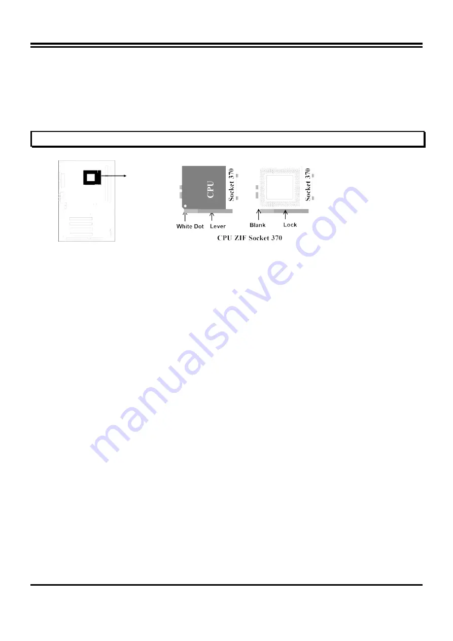
To install a CPU, first turn off your system and remove its cover. Locate the ZIF Socket and
open it by first pulling the lever sideways away from the socket then upwards to a 90-degree
right angle. Insert the CPU with the white dot as your guide. The white dot should point towards
the end of the level. The CPU has a corner pin for three of the four corners, the CPU will only fit
in the one orientation as shown as follow. With the added weight of the CPU fan, no force is
required to insert the CPU. Once completely inserted, hold down on the fan and close the
Socket’s lever.
IMPORTANT: You can setting the CPU ratio and Host Frequency in the BIOS setup on page
18
2-8 Expansion Cards
You must read the documentation come with expansion card for any hardware or software
settings that may be required to setup your specific card.
Installation Procedure:
1. Read the documentation from your expansion card.
2. Set any necessary jumpers on your expansion card.
3. Remove your computer’s cover.
4. Remove the bracket on the slot you intend to use.
5. Carefully align the card’s connectors and press firmly.
6. Secure the card on the slot with the screw you remove in step 4.
7. Replace the computer’s cover.
8. Setup the BIOS if necessary.
9. Install the necessary software drivers for your expansion card.
Assigning IRQs for Expansion Cards
Some expansion cards may require an IRQ to operate. Generally an IRQ must be exclusively
assigned to only one device. In an standard design there are 16 IRQs available but most of
them are occupied by the system and leaves 6 free for expansion cards.
With most recent device, the BIOS automatically assign an IRQ number to PCI expansion cards.
Please make sure there are no any of two devices use same IRQs, otherwise your computer
may experience some problems when those two devices are in use at the same time.
Assigning DMA Channels for Expansion Cards
Some devices may also need to use a DMA (Direct Memory Access) channel. DMA
assignments for this mainboard are handled the same way as the IRQ assignment process
described above. You can select a DMA channel in the PCI and PnP configuration section of the
BIOS Setup utility.
2-9 External Connectors
1. Power Connector: ATX Power Connector (20-pin block): PL1
8
Summary of Contents for BX2000
Page 5: ...2 2 BX2100 BX2000 Mainboard Diagram Figure 2 2 Only for BX2100 mainboard 4...
Page 37: ...The un selected area will be gray out 36...
Page 38: ...The un selected area will be gray out 37...
Page 40: ...BX2100 SPDIF IN An example of Portable CD Player Output to BX2100 Optical Input Setup 39...