7
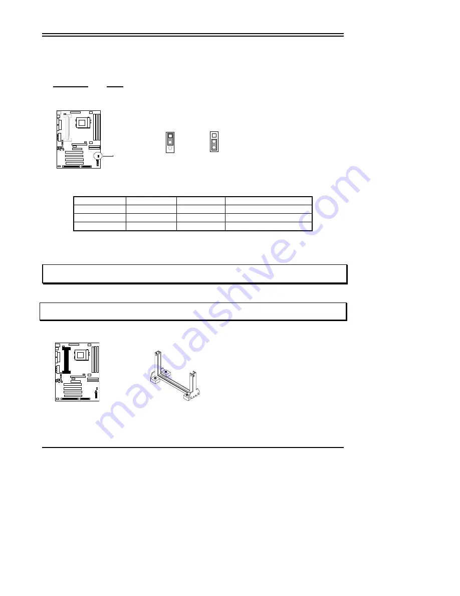
Connect a jumper Cap over this jumper for a few seconds, will clears information stored in the
CMOS RAM Chip that input by user, such as hard disk information and passwords. After
CLEAR CMOS, you must enter the BIOS setup (by holding down <DEL> during power-up) to re-
enter BIOS information (see BIOS SETUP).
Selections
JP16
Normal 1-2
(Default)
Clear
CMOS 2-3
(momentarily)
CMOS RAM (Normal / Clear CMOS Data)
JP16
JP16
Normal
1
2
3
Clear CMOS
1
2
3
2-6 System Memory (DRAM)
This mainboard supports three 168-pins DIMM modules, the Max Memory Size is 1.5GByte.
DIMM 1
DIMM 2
DIMM 3
System can be Accept or Not
168-pin DIMM
x x
Accept
168-pin DIMM
168-pin DIMM
x Accept
168-pin DIMM
168-pin DIMM
168-pin DIMM
Accept
2-7 Central Processing Unit (CPU)
2-7-1
The mainboard provides a Slot-1 for Pentium II/III processor. The CPU on board must
have a fan or heat sink attached to prevent overheating.
WARNING: Without a fan or heat sink, the CPU will overheat and cause damage to both the CPU
and the mainboard.
To install a CPU, first turn off your system and remove its cover. Locate the Slot- 1 and place
RETENTION MODULE as following:
IMPORTANT: You must set jumper U19,U20 for “Bus Frequency Selection” and “CPU Ratio” on
page6
depending on the CPU that you install.
1. Attach heat sink to the CPU.
2. Place Part A on Slot-1 and gently screw four corners on top of the main- board.
PART A
2-7-2
The mainboard also provides a 370-pin ZIF Socket 370. The CPU on mainboard must
have a fan attached to prevent overheating.
To install a CPU, first turn off your system and remove its cover. Locate the ZIF Socket and
open it by first pulling the lever sideways away from the socket then upwards to a 90-degree


