background image


35 

enabled, and when it is not lit, it means it is mute. Several 

output

 signals can usually be enabled 

at once. 

MP3 Player 

:  

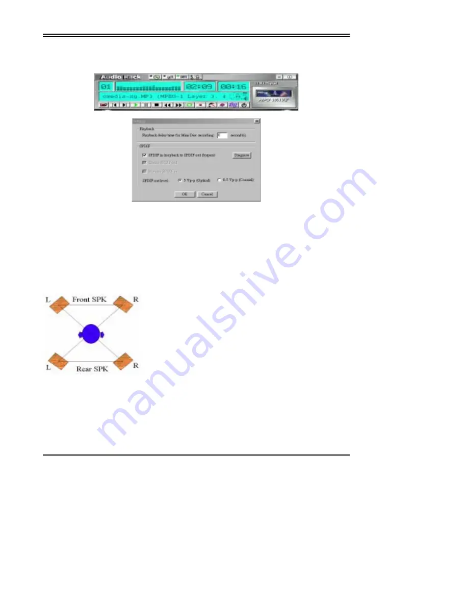
MP3 player can play both wave files and MP3 files. 


MP3 player while the loop function enables. 


The settings’ window while one of the SPDIF functions is enable. 

The 4 Speakers System 

This Audio Adapter provides 2 wave channels(front/rear), known as the 4 speakers system.  
When games or application programs via DirectSound® 3D or A3D® interface locate the sound 
sources to the  listener's back, the two rear speakers will work to enhance the rear audio 
positional effect, so as to complement the insufficiency of using only two front speakers to 
emulate the audio effect.  The following is the hardware installation and the software setups: 
1. The speaker installation. 
Connect the front pair speakers to the Line-out jack of the audio adapter, and then connect rear 
pair speakers to Line-in/Rear jack of the audio adapter.  The original Line-in can be moved to 
Aux-in. 
2. The positions of the speakers 

Put your speakers the way the following picture suggests, so as to avail yourself to the best 
audio result. 

3. The mixer setup 

There is a 4 speakers option in the volume control of the mixer,  and when you enable this option, 
it means the rear speakers are connected to Line-in/Rear jack.  When Line-in/Rear jack is 
connected to other external Line-in sources, please DO NOT enable this option in order to avoid 
hardware conflicts.  Regarding rear speaker option, you can turn on or turn off the output of the 
back speakers, and adjust the volume, to have the rear/front speakers have the same volume. 

4.The demo 

Summary of Contents for 994AN

Page 1: ...contained herein NO G03 994ANR4A Release date NOV 2000 Year 2000 compliant Trademark Pentium is registered trademark and MMX is a trademark of Intel corporation the other names and brands are the pro...

Page 2: ...P 17 3 1 STANDARD CMOS FEATURES 18 3 2 ADVANCED BIOS FEATURES 19 3 3 ADVANCED CHIPSET FEATURES 21 3 4 INTEGRATED PERIPHERALS 22 3 5 POWER MANAGEMENT SETUP 23 3 6 PnP PCI CONFIGURATIONS 24 3 7 PC HEALT...

Page 3: ...rt 66MHz 140MHz of Front Side Bus Frequency This function allow user select CPU Bus Frequency by the BIOS to approach Over Clock possibility Provide PC Health Monitoring to track CPU temperature syste...

Page 4: ...te Second ACPI supporting for OS Directed Power Management Ring In Wake up When Ring In the system can wake up from SMI Mode Ring In Power On When Ring In the system can power on automatic by this fun...

Page 5: ...r board Be sure there are no shipping and handling damages on the board before proceeding After opening the mainboard carton extract the system board and place it only on a grounded anti static surfac...

Page 6: ...I4 PCI 4 ZIF SO CKE T 370 C PU U10 DIMM2 DIMM3 DIMM2 DIMM3 DIMM1 DIMM1 SL1 JP15 AGP1 AGP JP2 JP3 IR1 JP16 SYSFAN IDE1 CPUFAN BIO S U4 FDD FDD JP9 WOL KE YL O C K R ST TBLE D TBSW HDL E D PS O N SPE AK...

Page 7: ...12 WOL Wake On LAN 3 pin Block P 12 Jumpers Connectors Option for motherboard that embedded Audio chip Item number Name Description Page JP4 On Board Sound Enable Disable 1 2 Disabled 2 3 Enabled p 13...

Page 8: ...66MHz 5 5x 550E 100 100MHz 5 5x 800 100 100MHz 8 0x 400 66 66MHz 6 0x 600E 100 100MHz 6 0x 800EB 133 133MHz 6 0x 466 66 66MHz 7 0x 600EB 133 133MHz 4 5x 850 100 100MHz 8 5x 500 66 66MHz 7 5x 650 100...

Page 9: ...7 1 The mainboard provides a Slot 1 for Pentium II III processor The CPU on board must have a fan or heat sink attached to prevent overheating WARNING Without a fan or heat sink the CPU will overheat...

Page 10: ...the processor s silicon die directly mounted to a pinned interposer substrate The pin grid array is partially populated and there may be surface mount components in the unpopulated central area of th...

Page 11: ...and debris Make sure the processor is fully inserted into the socket on all sides Step 3 Close the socket by lowering and locking the actuation lever Step 1 Remove the protective liner from the therma...

Page 12: ...ce the computer s cover 8 Setup the BIOS if necessary 9 Install the necessary software drivers for your expansion card Assigning IRQs for Expansion Cards Some expansion cards may require an IRQ to ope...

Page 13: ...ed on the full power will not come into the system board until the front panel switch is momentarily pressed Press this switch again will turn off the power to the system board PIN ROW 2 ROW1 1 3 3V 3...

Page 14: ...the floppy drives Floppy drive Connector Pin 1 7 Primary IDE Connector 40 pin block IDE1 This connector supports the provided IDE hard disk ribbon cable After connecting the single plug end to mainboa...

Page 15: ...The turbo LED will remain constantly lit while the system power is on You may wish to connect the Power LED from the system case to this lead See the figure below 12 Reset switch lead RST This 2 pin...

Page 16: ...small opening on system cases that support this feature you must also configure the setting through BIOS setup Use the four pins as shown on the Back View and connect a ribbon cable from the module t...

Page 17: ...ctor JP2 JP3 JP2 and JP3 are the connectors for CD Audio Input signal Please connect it to CD ROM CD Audio output connector 22 Audio and Game Connector AGC This Connector are 3 phone Jack for LINE OUT...

Page 18: ...This connector is for user that has Optical kit optional to provide other set of SPDIF INPUT and SPDIF OUTPUT function Optical kit Connector JP9 1 2 9 10 Chapter 3 AWARD BIOS SETUP This mainboard has...

Page 19: ...t Saving Esc QUIT F 9 Menu in BIOS Select Item F10 Save Exit Setup Time Date Hard Disk Type Figure 3 Note that a brief description of each highlighted selection is listed below The main menu includes...

Page 20: ...divided into many categories and each category may includes more than one setup items Please use the arrow keys to highlight the item and then use the PgUp or PgDn keys to select the value you want i...

Page 21: ...CC Checking Enabled Processor Number Feature Enabled Quick Power On Self Test Enabled First Boot Device Floppy Second Boot Device HDD 0 Third Boot Device LS ZIP Boot other Device Enabled Swap Floppy D...

Page 22: ...er boot device that is available if the other fails Swap Floppy Drive If the system has two floppy drives you can swap the logical drive name assignments The choice Enabled Disabled Boot Up Floppy See...

Page 23: ...ider making any changes would be if you discovered that data was being lost while using your system CMOS Setup Utility Copyright 1984 1999 Award Software Advanced Chipset Features Bank 0 1 DRAM Timing...

Page 24: ...ex Mode Disabled Half Duplex time out Enabled Item Help Menu Level Move Enter Select PU PD Value F10 Save ESC Exit F1 General Help F5 Previous Values F6 Fail Safe Defaults F7 Optimized Defaults Figure...

Page 25: ...anagement This category allows you to select the type or degree of power saving and is directly related to the following modes 1 HDD Power Down 2 Doze Mode 3 Suspend Mode There are four selections for...

Page 26: ...ts own special components This section covers some very technical items and it is strongly recommended that only experienced users should make any changes to the default settings CMOS Setup Utility Co...

Page 27: ...ned to Legacy ISA for devices compliant with the original PC AT bus specification PCI ISA PnP for devices compliant with the Plug and Play standard whether designed for PCI or ISA bus architecture Cho...

Page 28: ...creen If U19 is setting to 100MHz you can have 100 33 103 34 112 37 124 41 124 41 If U19 is setting to 133MHz you have the choice 133 33 133 44 140 35 Please turn off system power if the screen does n...

Page 29: ...thorized use of your computer You determine when the password is required within the BIOS Features Setup Menu and its Security option see Section 3 If the Security option is set to System the password...

Page 30: ...MONITOR III option for motherboard that embedded PC Health Software for Windows 95 98 Please Run X VIA HEALTH3 SETUP EXE NOTES 1 For Windows 95 user You must run SETUP EXE twice in order to complete t...

Page 31: ...by this software If there is an abnormal event happens it will pop up a window on screen to inform the user the abnormal situation Using the Software General Function 1 Power Supply Voltage VCORE Low...

Page 32: ...up warning message user can choose to activate Beep tone if there is error detected Beep tone will until the error is treated 4 3 Sound Driver Audio Rack Installation Option for Motherboard That Embe...

Page 33: ...We recommend that you install Microsoft Windows before you install this PCI sound card and you not install any other sound card device drivers in your current system 1 Turn on the computer and enter t...

Page 34: ...Start button move the highlight bar to Setting item and select the Control Panel 2 Double click Multimedia icon 3 Select Devices page and press Add button 4 Select Unlisted or Updated Driver item in L...

Page 35: ...nter s Button Bar or toggle it off MIDI Player Wave Player and CD Player CD Player above similar to Wave Player and MIDI Player Sel or Trk field If you have multiple selections in your playlist this s...

Page 36: ...change the output of an individual output type move its slider Line in Rear Controls the audio hardware s Line In or Line Out levels Line levels might be for an externally attached cassette player for...

Page 37: ...hardware installation and the software setups 1 The speaker installation Connect the front pair speakers to the Line out jack of the audio adapter and then connect rear pair speakers to Line in Rear j...

Page 38: ...that embedded PC Health chip The Optical Kid includes z Optical Module z Optical Cable z Software DVD driver An example of optical kit with MD connection The application program setup please install C...

Page 39: ...37 When all the procedures have been completed there will be an infrared signal coming from the SPDIF OUT of the optical fiber of the sound card...

Page 40: ...m may cause severe damage to the eyes For your safety please point the output end to a piece of white paper to check if thebeam is in function Please connect the output signal to the MD input then pla...

Page 41: ...longer than three seconds between each track the MD can not recognize the tracks and will record all of them into one It is recommended that you set the gap time to 3 5 seconds to meet all type of MD...

Page 42: ...can only be applied to SPDIF IN OUT mode it does not apply to other modes such as the four channels or the analog No sound will be heard while in playback yet it can be recorded The un selected area w...

Page 43: ...ea will be gray out The un selected area will be gray out You can double click this circuit icon to have the following setting box By means of this setting box you can also complete the above mentione...

Page 44: ...42 SPDIF IN for motherboard that embedded Audio chip An example of Portable CD Player Output to Main Board Optical Input Setup...

Page 45: ...43 When the connection is done please go to the Start menu and select PCI Audio Applications Audio Environment Setting Loopback bypass mode setup CD ROM Digital Output to SPDIF IN Setup...

Page 46: ...44 When the connection is done please go to the Start menu and select PCI Audio Applications Audio Environment Setting...

Page 47: ...procedures Now you can insert the CD into the CD ROM drive then activate C MEDIA CD player and push the play button to do the recording job Please note that you have to set the MD in the simultaneous...

Page 48: ...ll corresponding IDE driver AGP Bus driver VGA This item appeared when your motherboard embedded VGA chip and allows you install corresponding display driver You will not see this item appear on the s...

Reviews: