


JX2-PRN1
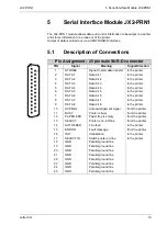
5 Serial Interface Module JX2-PRN1
Jetter AG
21
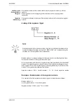
Coding of the registers:
3yyz
Module number 1 is always assigned to the basic control unit. Starting from there,
the module numbers are being counted left to right.
For communication with the CPU, 3 registers have been provided by the JX2-PRN1
module. The operating system version number of the module can always be read
from register 9. The other module registers are being defined by the function of the
module. The registers are addressed as follows:
Register number = 3000 + (module number - 2) * 10 + local register number
Examples: Determination of the register numbers
The number of the first expansion module’s register is determined as follows:
Module number = 2
Local register number = 3 (control register)
Register number = 3000 + (2-2) * 10 +3 = 3003
Interface with
the Application
Program
The interface between the module and the user's program is made up of three
registers.
These registers are for configuring of the modules and for querying status
information.
Register
Addressing
The register address is made up of the module number and the respective register
number.
Note!
For determination of the module number, only the non-intelligent modules will be
counted. Intelligent modules, such as SV1, SM1D, PID1, etc., located among the
modules, are not being taken into consideration.


