background image

4

Safety Warnings

• Before use, please read the user manual and safety warnings carefully, and make sure you understand and accept all the safety 

instructions. The user will be responsible for any loss or damage caused by improper use.

• Failure to use correct charger can result in fire and explosion.

 Failure to use correct charger can result in fire and explosion.

• Before each cycle of operation, the operator shall perform the preoperation checks specified by the manufacturer: That all guards and pads 

originally 

supplied by the manufacturer are in proper place and in serviceable condition; That the braking system is functioning properly; That any and 

all axle guards, chain guards, or other covers or guards supplied by the manufacturer are in place and in serviceable condition; That tires 

are in good condition, inflated properly, and have sufficient tread remaining; The area that the product is to be operated should be safe and 

suitable for safe operation.

• Components shall be maintained and repaired in accordance with the manufacturer’s specifications and using only the manufacturer’s 

authorized replacement parts with installation performed by dealers or other skilled persons.

• Warning against recharging non-rechargeable batteries.

• Don’t allow hands, feet, hair, body parts, clothing, or similar articles to come in contact with moving parts, wheels, or drive train, while the 

motor is running.

• This product should not be used by children or persons with reduced physical, sensory or mental capabilities, or lack of experience and

knowledge, unless they have been given supervision or instruction (IEC 60335-1/A2:2006).

• Unsupervised children should not play with the product (IEC 60335-1/A2:2006).

• Adult supervision is required.

• The rider should not exceed 77 lb.

• Units shall not be operated to perform racing, stunt riding, or other maneuvers, which may cause loss of control, or may cause uncontrolled 

operator

passenger actions or reactions.

• Never use near motor vehicles.

• Avoid sharp bumps, drainage grates, and sudden surface changes. Ride-on may suddenly stop.

• Avoid streets and surfaces with water, sand, gravel, dirt, leaves, and other debris. Wet weather impairs traction, braking, and visibility.

• Avoid riding around flammable gas, steam, liquid, or dust that could cause fire.

• Operators shall adhere to all of the manufacturer’s recommendations and instructions, as well as comply with all laws and ordinances:

Units without headlights shall be operated only with adequate daylight conditions of visibility, and; Owners shall be encouraged to highlight 

(for conspicuity) using lighting, reflectors, and for low-riding units, signal flags on flexible poles.

• Persons with the following conditions shall be cautioned not to operate: Those with heart conditions; Pregnant women; Persons with head,

back, or neck ailments, or prior surgeries to those areas of the body; and persons with any mental or physical conditions that may make 

them susceptible to injury or impair their physical dexterity or mental capabilities to recognize, understand, and perform all of the safety 

instructions and to be able to assume the hazards inherent in unit use.

• Do not ride at night.

• Do not ride after drinking or taking prescription medication.

• Do not carry items when riding.

• Never operate the product barefooted. 

• Always wear shoes and keep shoelaces tied.

• Make sure your feet are always placed securely on the deck.

• Operators always shall use appropriate protective clothing, including but not limited to a helmet, with appropriate certification, and any

other equipment recommended by the manufacturer: Always wear protective equipment such as helmet, knee pads, and elbow pads.

• Always give way to pedestrians.

• Be alert to things in front and far away from you.

• Do not allow distractions when riding, such as answering the phone or engaging in any other activities.

• The product cannot be ridden by more than one person.

• When you ride the product along with other riders, always keep a safe distance to avoid a collision.

Summary of Contents for Safara JSAFAR-RED

Page 1: ...IMPORTANT READ CAREFULLY AND RETAIN FOR FUTURE REFERENCE MODELS JSAFAR RED JSAFAR PNK JSAFAR NAV Safara Kids 12V Ride On Aguideforyourride...

Page 2: ......

Page 3: ...Jetson stoptworidingrules Besafe Havefun...

Page 4: ...g Started Starting Notes Assembling the Steering Brackets Assembling the Rear Wheels Assembling the Front Wheels Inserting the Seat Attaching the Rear Tailstock Attaching the Steering Wheel Attaching...

Page 5: ...54 54 56 57 58 59 60 2 Making Moves Fastening the Seatbelt Setting Up Using the Remote Control Activating Horn Engine Sounds A Guide to Your Dashboard Riding the Safara Helmet Safety Care Maintenance...

Page 6: ...ontrolled operator passenger actions or reactions Never use near motor vehicles Avoid sharp bumps drainage grates and sudden surface changes Ride on may suddenly stop Avoid streets and surfaces with w...

Page 7: ...E This equipment has been tested and found to comply with the limits for a Class B digital device pursuant to Part 15 of the FCC Rules These limits are designed to provide reasonable protection agains...

Page 8: ...period of time from the date of original retail purchase when used in accordance with Jetson s user manuals refer to ridejetson com support Under this warranty you will be able to direct your claims t...

Page 9: ......

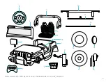
Page 10: ...X2 LEFT RIGHT BACKSHAFT BASE X2 LEFT RIGHT GEAR BOX X2 LEFT RIGHT STEERING BRACKET PRE ATTACHED WITH FRONT WHEEL AXLES STEERING BRACKET PRE ATTACHED REAR AXLE FRONT WHEEL X2 REAR WHEEL DRIVE WHEEL X2...

Page 11: ...M S P 9 1 2 3 9 14 16 13 15 10 11 12 4 5 6 7 17 8 18 NOTE IMAGES MAY NOT REFLECT EXACT APPEARANCE OF ACTUAL PRODUCT...

Page 12: ...TACHED PLUS 1 SPARE WRENCH X2 DOUBLE SIDED FLAT HEAD A AND PHILLIPS HEAD B SCREWDRIVER WITH ATTACHABLE HANDLE C NOTE SOME HARDWARE USED FOR ASSEMBLY IS PRE ATTACHED ON PARTS OF THE SAFARA LOCATIONS AN...

Page 13: ...INCLUDED BATTERIES NEEDED FOR STEERING WHEEL 2 AA NOT INCLUDED MOTOR 40W 2 PRODUCT WEIGHT 42 LB PRODUCT DIMENSIONS 45 0 L 30 0 W 26 0 H TIRE SIZE 12 5 4 75 CHARGER UL LISTED DC12V CHARGING TIME 8 12 H...

Page 14: ...12 OnlineResources Scanforourmost updatedSafara onboardingmaterials andsupportresources...

Page 15: ...ND FOOT WILL BE IT MIGHT BE USEFUL TO HAVE EXTRA HANDS FOR ASSEMBLY GRAB AN ASSISTANT 1 1 StartingNotes 1 GettingStarted WARNING FAILURE TO COMPLY WITH THE FOLLOWING INSTRUCTIONS MAY RESULT IN INJURY...

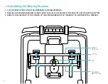
Page 16: ...Brackets 1 FLIP THE BODY OVER SO THAT THE UNDERSIDE IS FACING UPWARDS 2 RELEASE THE STEERING BRACKET B AND FRONT AXLE A AT THE FRONT OF THE BODY BY CUTTING OFF THE ZIP TIES 3 REMOVE THE LARGE NUT AT T...

Page 17: ...15 4 REMOVE THE WASHER UNDERNEATH THE NUT AND SET THE HARDWARE ASIDE 5 LIFT THE STEERING BRACKET OFF THE BODY STEERING BRACKET B...

Page 18: ...AND REMOVE THE BOLTS FROM THE SMALL NUTS ON BOTH SIDES OF THE STEERING BRACKET BY TURNING THE BOLTS COUNTERCLOCKWISE WITH THE PHILLIPS HEAD SCREWDRIVER SET THE HARDWARE ASIDE STEERING BRACKET B PHILL...

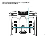
Page 19: ...17 7 ROTATE THE FRONT WHEEL AXLES ON THE STEERING BRACKET UNTIL THEY ARE IN LINE WITH THE BRACKET AND EXTENDING OVER THE SIDES OF THE BODY FRONT WHEEL AXLE STEERING BRACKET B BODY...

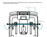
Page 20: ...S ARE MET THE TAB EXTENDING FROM THE MIDDLE OF THE BRACKET IS CLOSER TO THE BODY THE HOLE IN THE TAB IS AROUND THE FRAME BOLT FROM WHICH IT CAME THE HOLES ON THE ENDS OF THE BRACKET ARE ALIGNED WITH T...

Page 21: ...19 WASHER NUT 9 SLIDE THE WASHER BACK ON THE FRAME BOLT AND PUT THE LARGE NUT ONTO THE BOLT BY TWISTING IT ON CLOCKWISE TIGHTEN THE NUT WITH A WRENCH WRENCH...

Page 22: ...SIDE OF THE STEERING BRACKET B FROM UNDERNEATH TWIST A NUT CLOCKWISE ONTO THE END OF EACH BOLT HOLD THE BOLT STEADY WHILE YOU FULLY TIGHTEN THE NUT CHECK THAT THE STEERING BRACKET B IS SECURELY ATTAC...

Page 23: ...21 1 3 AssemblingtheRearWheels 1 IN THE REAR OF THE BODY PLACE THE TWO BACKSHAFT BASES INTO THEIR CORRESPONDING SLOTS BACKSHAFT BASE...

Page 24: ...22 IMPORTANT ENSURE THAT THE BACKSHAFT BASE MARKED R IS PLACED ON THE SIDE OF THE BODY MARKED R AND THAT THE BACKSHAFT BASE MARKED L IS PLACED ON THE SIDE OF THE BODY MARKED L BACKSHAFT BASE BODY...

Page 25: ...SET OF ALIGNED HOLES IN THE BACKSHAFTS AND BODY BY TWISTING IT IN CLOCKWISE WITH THE PHILLIPS HEAD SCREWDRIVER 10 TOTAL SCREWS 3 CHECK THAT THE BACKSHAFTS ARE SECURED TO THE BODY SCREW PHILLIPS HEAD S...

Page 26: ...24 REAR AXLE WASHER WASHER LARGE NUT LARGE NUT 4 LOOSEN AND REMOVE THE LARGE NUTS ON THE END OF THE REAR AXLE BY TWISTING THEM OFF COUNTERCLOCKWISE 5 REMOVE THE WASHERS FROM THE AXLE...

Page 27: ...25 6 FROM ONE SIDE SLIDE THE REAR AXLE THROUGH THE SIDE HOLES IN BOTH BACKSHAFT BASES 7 CENTER THE AXLE REAR AXLE BACKSHAFT BASE...

Page 28: ...THE END OF THE REAR AXLE ON THE LEFT SIDE L OF THE BODY MARKED 9 WHILE PUSHING THE GEAR BOX ALL THE WAY UP TO THE BODY PUSH THE WIRES ON THE GEAR BOX INTO THE HOLE IN THE SIDE OF THE BODY 10 REPEAT ST...

Page 29: ...27 11 CHECK THAT THE GEAR BOXES ARE SNUG UP TO THE BODY AND THE WIRES FROM BOTH GEAR BOXES ARE FULLY INSIDE THE BODY GEAR BOX BODY...

Page 30: ...28 REAR WHEEL DRIVING WHEEL 12 LEADING WITH THE SIDE OF THE WHEEL THAT HAS AN EXTENSION IN THE CENTER SLIDE ONE REAR WHEEL DRIVING WHEEL ONTO EACH END OF THE AXLE REAR AXLE...

Page 31: ...29 13 PUSH THE WHEELS UP AGAINST THE GEAR BOXES GEAR BOX REAR WHEEL...

Page 32: ...15 SIMULTANEOUSLY TIGHTEN BOTH NUTS BY TURNING THEM BOTH CLOCKWISE WITH THE WRENCHES IMPORTANT TAKE CARE NOT TO OVER TIGHTEN THE NUTS AS OVER TIGHTENING CAN CAUSE THE WHEELS TO CRACK STOP TURNING THE...

Page 33: ...31 16 LEADING WITH THE OPEN SIDE OF THE HUB CAB POP A HUBCAP INTO PLACE IN THE CENTER OF EACH REAR WHEEL OVER THE NUT HUB CAP REAR WHEEL NUT REAR AXLE...

Page 34: ...32 STEERING BRACKET A FRONT WHEEL AXLE 1 4 AssemblingtheFrontWheels 1 REMOVE THE LARGE NUT FROM EACH FRONT WHEEL AXLE BY TWISTING IT OFF COUNTERCLOCKWISE LARGE NUT WASHER...

Page 35: ...33 2 REMOVE ONE WASHER FROM EACH FRONT WHEEL AXLE AND SET IT ASIDE WITH THE NUT LEAVE THE SECOND WASHER ON EACH AXLE WASHERS LARGE NUT FRONT WHEEL AXLE...

Page 36: ...34 FRONT WHEEL 3 LEADING WITH THE FLAT SIDE OF THE WHEEL SLIDE ONE FRONT WHEEL ONTO EACH FRONT AXLE FRONT AXLE...

Page 37: ...35 4 PUSH THE WHEELS ALL THE WAY ONTO THE AXLE SO THAT THEY ARE SNUG AGAINST THE WASHERS WASHER FRONT WHEEL FRONT WHEEL AXLE...

Page 38: ...F THE AXLE 6 SIMULTANEOUSLY TIGHTEN BOTH NUTS BY TURNING THEM BOTH CLOCKWISE WITH THE WRENCHES IMPORTANT TAKE CARE NOT TO OVER TIGHTEN THE NUTS AS OVER TIGHTENING CAN CAUSE THE WHEELS TO CRACK STOP TU...

Page 39: ...37 7 LEADING WITH THE OPEN SIDE OF THE HUB CAB POP A HUBCAP INTO PLACE IN THE CENTER OF EACH REAR WHEEL OVER THE NUT FRONT AXLE HUB CAP NUT...

Page 40: ...38 1 5 InsertingtheSeat 1 FLIP THE BODY OVER SO IT IS UPRIGHT 2 ALIGN THE COUPLERS IN THE SEAT BOX WITH WIRES OF THE SAME COLORS SEAT BOX RECEIVING COUPLER INSERTION COUPLER...

Page 41: ...NTO THE RECEIVING COUPLERS NOTE MAKE SURE TO CONNECT EACH COUPLER WITH THE RECEPTOR OF CORRESPONDING COLOR 4 CHECK THAT THE CONNECTIONS ARE SECURE IMPORTANT ATTACH ELECTRICAL COMPONENTS WITH CAUTION R...

Page 42: ...T SECTION 6 POSITION THE SEAT BOTTOM SUCH THAT THE CURVED SECTION IS FORWARD AND THE CROSSHATCH SECTION IS FACING UP 7 POSITION THE SEAT BACK SUCH THAT THE HEADRESTS ARE UP AND THE CROSSHATCH IS FORWA...

Page 43: ...E CONNECTED SEAT BACK AND SEAT BOTTOM INTO THE SEAT SECTION AND SLIDE IT BACK SUCH THAT THE TWO REMAINING TABS IN THE SEAT BOTTOM FIT INTO THE TAB HOLES AT THE REAR OF THE SEAT SECTION SEAT BACK SEAT...

Page 44: ...SET OF ALIGNED HOLES IN THE SEAT BACK AND BODY AND SEAT BOTTOM AND BODY BY TWISTING IT CLOCKWISE 4 TOTAL TIGHTEN THE SCREWS WITH THE PHILIPS HEAD SCREWDRIVER 11 CHECK THAT THE SEAT BOTTOM AND SEAT BAC...

Page 45: ...tachingtheRearTailstock 1 POSITION THE REAR TAILSTOCK OVER THE BODY SUCH THAT THE EXTENSION LEGS ARE IN FRONT AND THE 4 LEGS ARE ALIGNED WITH THE 4 HOLES IN THE REAR OF THE BODY 2 POP THE LEGS INTO TH...

Page 46: ...44 3 CHECK THAT THE REAR TAILSTOCK IS SECURELY ATTACHED REAR TAILSTOCK...

Page 47: ...gWheel 1 ALIGN THE STEERING WHEEL STEM WITH THE STEERING POST AT THE FRONT OF THE RIDER AREA ROTATE THE STEERING WHEEL UNTIL THE TAB HOLES IN THE STEM ARE ALIGNED WITH THE TABS IN THE POST TAB HOLE ST...

Page 48: ...46 2 PUSH THE STEERING WHEEL STEM ONTO THE STEERING POST 3 CHECK THAT THE TABS ON THE POST ARE CLICKED INTO THE HOLES IN THE STEM AND THAT THE STEERING WHEEL IS SECURE STEERING WHEEL...

Page 49: ...AttachingtheWindshield 1 POSITION THE WINDSHIELD OVER THE FRONT OF THE BODY SUCH THE REFLECTORS ARE AT THE TOP FACING FORWARD 2 POP THE WINDSHIELD INTO ITS CORRESPONDING SLOT IN THE BODY BODY REFLECTO...

Page 50: ...NED HOLES IN THE WINDSHIELD AND BODY BY TWISTING IT IN CLOCKWISE 2 TOTAL TIGHTEN THE SCREWS WITH THE PHILLIPS HEAD SCREWDRIVER 4 CHECK THAT THE WINDSHIELD IS SECURELY ATTACHED TO THE BODY WINDSHIELD B...

Page 51: ...deMirrors 1 POSITION THE SIDE MIRRORS ON THE SIDE OF THE WINDSHIELD SUCH THAT THE MIRROR SIDE IS FACING THE RIDER AND THE SIDE WITH THE STEM IS CLOSEST TO THE WINDSHIELD 2 POP THE STEMS INTO THE DESIG...

Page 52: ...50 3 ENSURE THAT THE SIDE MIRRORS ARE SECURED TO THE BODY SIDE MIRROR BODY...

Page 53: ......

Page 54: ...D IN GREEN THEN CHARGE ONLY UNTIL THE BATTERY POWER IS FULL 8 TO 12 HOURS PER SESSION 1 PLUG THE CHARGING CABLE INTO THE WALL AND THEN PLUG THE CHARGER INTO THE CHARGING PORT 2 WHEN THE INDICATOR LIGH...

Page 55: ...R BEST BATTERY HEALTH CHARGE THE BATTERY FULLY DURING EACH CHARGING SESSION UP TO 12 HOURS NEVER LEAVE YOUR BATTERY CHARGING OVERNIGHT OR FOR EXTENDED PERIODS OF TIME DO NOT ATTEMPT TO REMOVE OR DISAS...

Page 56: ...2 2 SettingUp UsingtheRemoteControl YOU MAY NEED TO PAIR THE REMOTE CONTROL WITH THE VEHICLE UPON FIRST USE PRE PAIRED ON SOME MODELS THE REMOTE CONTROL ALSO NEEDS TO BE PAIRED WITH THE VEHICLE AGAIN...

Page 57: ...TEN THE SCREW IN THE HOLE BY TURNING IT CLOCKWISE WITH THE SCREWDRIVER TO PAIR THE REMOTE CONTROL WITH YOUR SAFARA 1 PRESS AND HOLD THE MATCH BUTTON FOR 2 TO 4 SECONDS THE INDICATOR LIGHTS ON THE REMO...

Page 58: ...THE HORN AND ENGINE SOUNDS THEY ARE NOT NECESSARY FOR RIDING TO INSERT BATTERIES IN THE STEERING WHEEL 1 LOOSEN THE SCREW ON THE BATTERY COMPARTMENT BY TWISTING THE SCREW COUNTERCLOCKWISE WITH THE PHI...

Page 59: ...ILL ILLUMINATE WHENEVER THE SAFARA IS POWERED ON 2 4 AGuidetoYourDashboard TOGGLE THE SWITCHES ON THE DASHBOARD TO POWER ON OFF SWITCH FROM FAST TO SLOW AND CHANGE DIRECTIONS FROM FORWARD TO REVERSE E...

Page 60: ...TO POWERING ON THE SAFARA TO GO PUSH THE ACCELERATOR PEDAL TO MOVE THE SAFARA ACCORDING TO THE SPEED FAST OR SLOW AND DIRECTION FORWARD OR BACKWARD IN WHICH YOU HAVE THE VEHICLE SET TO SLOW DOWN EASE...

Page 61: ...HELMET APPROPRIATE CLOTHING SHOES AND SAFETY GEAR AVOID CLOTHING THAT CAN GET CAUGHT INTO OR UNDER THE WHEELS CLOSED TOE FLAT SHOES ARE RECOMMENDED WEAR AN ASTM F1492 APPROVED HELMET AND PROTECTIVE G...

Page 62: ...TORING THE SAFARA STORE THE SAFARA INDOORS AND IN A DRY PLACE COVER THE SAFARA TO PROTECT IT AGAINST DUST FULLY CHARGE THE BATTERY BEFORE STORING FOR EXTENDED PERIODS OF TIME ONCE IN STORAGE CHARGE TH...

Page 63: ...sure to leave a review at ridejetson com reviews We can t wait to hear from you Stayconnected Be sure to follow ridejetson on social media to learn about fantastic offers giveaways and all the latest...

Page 64: ...hejiang China Imported by Jetson Electric Bikes LLC P O Box 320149 775 4th Ave 2 Brooklyn NY 11232 www ridejetson com Questions Letushelp Made in China Date Code 08 2023 Document Edition v2 1 2023 JET...

Reviews: