background image

computer radio control system

EN

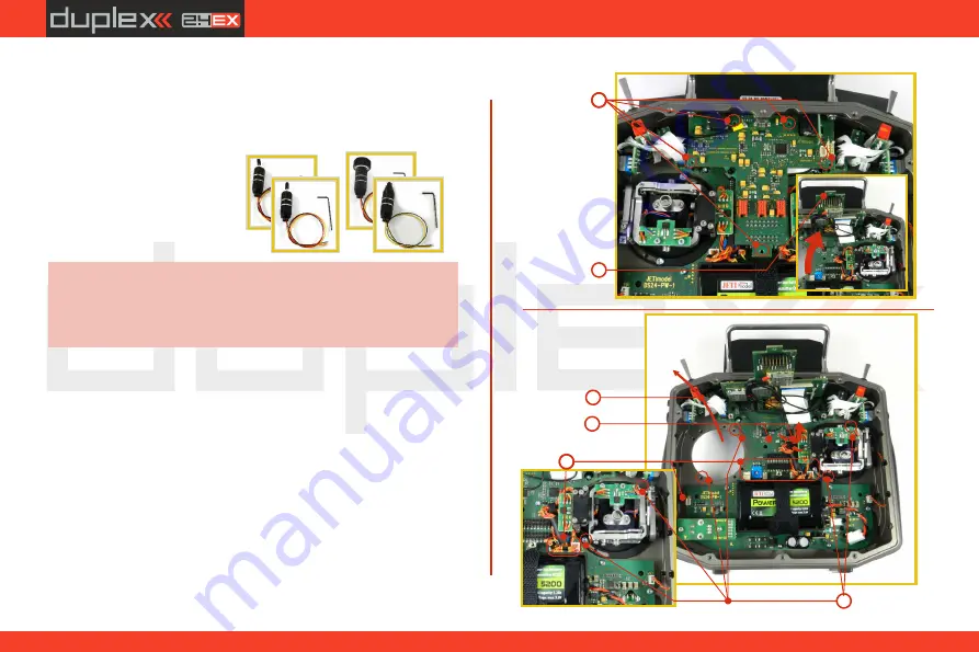
4.3.7    Transmitter  Gimbals  with  Switch  or  Button   
 

  Installation

If you want to operate the DS-24 transmitter using the optional stick 
end switch or button functions, you must purchase one or more of 
these separately:

 Stick with 2-position switch

 Stick with 3-position switch

 Stick with push-button

 Stick with potenciometer

For installation of the optional gimbal stick ends with 
switches/buttons  we  recommend  that  you  send  your 
transmitter  to  one  of  the  factory  authorized  service 
centers or to your authorized dealer.

Advice:

1. 


Switch off the transmitter and remove the 8 screws that secure 


the radio back cover. Next, remove the radio back cover. Be sure 


to disconnect the transmitter battery pack connector .

2.


Remove the screws of the upper printed circuit board (the "

T

plate).

3.


Remove the "

T

" circuit board by grasping the plate by its edges 


near where the bottom fastener goes. Gently lift the board to   


disconnect  its  connectors  from  the  board  below.  Once   


disconnected, tilt the board upward toward the display so that 

it is out of the way.

4.


Disconnect the control stick assembly wires from the  Tx board.


(4  wires  

).

X, Y, S,M

5.


Remove the stick assembly connecting wires from their holders 


on the main board.

X

Y

S

M

2

3

4

X

Y S

S

Y

X

5

7

6

M

M

30

Summary of Contents for duplex DS-16 II

Page 1: ...computer radio control system EN CZECH REPUBLIC DC DS 16 II 2 4GHz 900MHz NG Dual Band System EN FW 5 00 Part I User Manual...

Page 2: ...computer radio control system EN 2...

Page 3: ...n Adjustment 15 3 3 4 Ratchet Tension Adjustment 15 3 3 5 Throttle stick travel adjustment 16 3 3 6 Changing the transmitter mode 16 3 3 7 Transmitter Gimbals with Switch or Button Installation 17 3 4...

Page 4: ...d 37 5 Help mode 38 6 RF Transmitter Modules 39 7 Transmitter Powering ON OFF 39 7 1 Transmitter Powering ON 41 7 2 TransmitterTurning OFF 41 7 3 Transmitter Restart 41 8 Initialswitching on 42 8 1 Ma...

Page 5: ...Connection 64 10 1 Memory System Files 64 10 2 Update Firmware 64 10 3 Sounds Alarms Acoustic Updates 64 10 4 System Backup 65 10 5 PC Joystick 65 10 6 Telemetry Data Logging 65 10 7 Copying models be...

Page 6: ...tuitive setup procedurefordisplayingtelemetricdata The DUPLEX EX family of products have been equipped with an improved real time telemetry system which can be viewed on the LCD transmitter display Th...

Page 7: ...ly developed by JETI model in the Czech Republic This system has beenreliablyusedformanyyears Duplex 900MHz NG Next Generation the DC DS 16 II transmitters feature a backup wireless system for unmatch...

Page 8: ...trimmingfunction Swappable and Assignable Switches all of the switches on the DC DS transmitters 2 or 3 position can be easily moved and assigned to create a custom configuration that works best for y...

Page 9: ...s containtheanswerstoyourquestions 2 Distributor Manufacturer You may also find support at your local hobby shop distributor or directlywiththemanufacturerJETImodels r o 3 ServiceandWarrantyCoverage J...

Page 10: ...stallationKey Set 4 5 HEX1 5 TORX10 CleaningCloth InstructionManuals 6 2 4 5 6 3 1 6 DC 16 II Package Contents 1 2 4 5 6 3 1 2 3 JETI DS 16II Transmitter Wall Power Supply JETI DS Transmitter Aluminum...

Page 11: ...crophone Active Active Gyro Settings 3 3 Servo Balancer Active Active Function Curves Active Active Throttle Limiter heli Active Active Parameter DC 16 II DS 16 II Variometer Active Active Flight Mode...

Page 12: ...5 DigitalTrimsfortheRightStickT1 T2 6 RightSideControlLever5 7 LeftSideControlLever6 8 RotaryControlKnob7 9 RotaryControlKnob8 10 LCDDisplay 11 FunctionButtonsF1 F5 12 TransmitterOn OffPowerSwitch 13...

Page 13: ...ryPack 25 MemoryCardMicroSD8GB 26 PPMOutputConnector 27 LeftGimbalAssembly 28 RightGimbalAssembly 29 2 4GHzModule 30 900MHzModuleNG NextGeneration 31 PPMInput Output 32 BatteryConnector 3 2 Assembly I...

Page 14: ...ck length 3 Adjust the lower part to support the top part of thestickend 4 Finally secure by tightening both parts to eachother Ifyouhaveinstalledoptionalstickswithswitchorbuttonends makesurethatwhile...

Page 15: ...nd remove the 10 screws that secure the radio back cover Next remove the radio back cover Be sure to disconnect the transmitter battery pack connector 2 Use indicated machine adjustment screws to chan...

Page 16: ...screws After making a limit the throttle stick travel you must re A B 2 3 3 6 Changing the transmitter mode The transmitter is equiped with universal multimode gimbals Both gimbalsareidenticalandcanbe...

Page 17: ...dvice 1 Switchoffthetransmitterandremovethe10screwsthatsecure theradiobackcover Next removetheradiobackcover Be sure to disconnect the transmitter battery pack connector 4 A Tightenthescrew 5 D E Tigh...

Page 18: ...stick shaft and through the gimbal opening in order to prevent damaging the connecting cables The safest method is to remove the small set screw from the side of the stick housing to allow theswitcho...

Page 19: ...Sf 3 positionshortswitch Sg 3 positionlongswitch Sh 2 positionshortswitch Si 2 positionshortswitch Sj 3 positionlongswitch After the switch has been installed into the stick assembly you have tore con...

Page 20: ...itter gimbals are used for controlling the basic flight functionslikethrottle roll aileron pitch elevator andyaw rudder Immediately under the transmitter gimbal sticks you can see four push buttonswhi...

Page 21: ...position the transmitter LCD display shows the status and condition of the batterypack TheLi Ionbatteryisfactoryinstalled 3 6 1Charging The DC 16 II transmitter can be charged with the included wall...

Page 22: ...th your body This might increase likelihoodofrangeproblem Warning 3 7 PPM Input Output Connector The PPM output is accessible via internal connector labeled B This connector features a non stabilized...

Page 23: ...3 9 Change SD Card Disconnectthebatteryplug To open the SD card holder use a fingernail to push the metal frame to the right and then lift it carefully The micro SD card can now be removed Forinstalla...

Page 24: ...StickT3 T4 5 DigitalTrimsfortheRightStickT1 T2 6 RightSideControlLever5 7 LeftSideControlLever6 8 RotaryControlKnob7 9 RotaryControlKnob8 10 LCDDisplay 11 FunctionButtonsF1 F5 12 TransmitterOn OffPowe...

Page 25: ...mputer radio control system EN 27 BatteryConnector 28 TransmitterBatteryPack 29 PPMOutputConnector 30 LeftGimbalAssembly 31 RightGimbalAssembly 32 SDCard 4 2 Assembly Identification 28 27 29 30 31 32...

Page 26: ...he lower part to support the top part of thestickend 4 Finally secure by tightening both parts to eachother If you have installed optional sticks with switch or buttonends makesurethatwhileadjustingth...

Page 27: ...ust each gimbal sspringtoyourdesiredtension 1 Switch off the transmitter and remove the 8 screws that secure theradiobackcover Next removetheradiobackcover Be sure to disconnect the transmitter batter...

Page 28: ...tomize your radio s feel Each tension is set by a different machinescrew 3 Reconnect transmitter battery pack and reinstall radio back coverandcoverscrews 4 3 5 Throttle stick travel adjustment Thethr...

Page 29: ...sition gas 1 A Loosenthescrew 2 C LifttheleverBsoasitispossibletoarrestthelock 3 C Turn the lock 90 in the direction of the arrow and arrest the lever intheupperposition B 4 A Tightenthescrew 5 D E Ti...

Page 30: ...urauthorizeddealer Advice 1 Switch off the transmitter and remove the 8 screws that secure the radio back cover Next remove the radio back cover Be sure todisconnectthetransmitterbatterypackconnector...

Page 31: ...rew from the side of the stick housing to allow the switch or knob internals to remain stationary while yourotatethestickhousingforheightadjustment 11 Pass the switch wires through the same gimbal ope...

Page 32: ...the connectors of the T printed circuit board into the body of transmitter and then carefully insert the T plate into its connectors on the mainboard Becarefulwhilehandlingthewiresunderneaththe T pla...

Page 33: ...SwitchConfiguration for the DS 24Transmitter Sa 3 position short switch Sb 2 positionlongswitch Sc 2 position short switch Sd 2 positionlongswitch Se 3 positionlongswitch Sf 2 position short switch Sg...

Page 34: ...circuit board of the transmitter See the orientation above The cable has to be insertedtotheconnectorthatmatchesthepositiononthefront panelwheretheswitchisinstalled 5 Reconnect transmitter battery pac...

Page 35: ...built in advanced battery management and charging circuit In switched on position the transmitter LCD display shows the status and condition of the batterypack TheLi Ionbatteryisfactoryinstalled 4 6...

Page 36: ...use of other battery packs will void the warranty Warning If the transmitter battery has been disconnected for longerthan1minute thetimeanddatewillbedeleted Note 3 2 4 7 PPM Input Output Connector The...

Page 37: ...check If you are operating a model with a DS 24 transmitter do not shield and avoid contact of the transmitter antennas see Photo with your body Warning The transmitter 2 4GHz antenna locations are s...

Page 38: ...on mark iconappearsintheupperrightcornerofthescreen Ifyousee 1 this icon you can press the menu button briefly to call up the help mode for the current item you have highlighted in the respective tran...

Page 39: ...cond RF module In an instant you have created a dual redundant flying system with two receivers and two RF modules Thisgreatlyimprovessafetyandreliabilitysinceboth RFmodules alternate their communicat...

Page 40: ...eceiverinthe R1 R2 slotoftheCentralBox TheRSat900NGisconnectedtothe R3 slotoftheCentralBox BothreceiversaresettoEXBusoutput ConnectingtheRSat 900NGdirectlytoaPrimaryreceiver The RSat 900 NG receiver i...

Page 41: ...guration Fastswitch on If you want to find out the battery status on a switched off transmitterjustpushthebutton Power andtheinitialscreen with the battery status will appear If you do not confirm tur...

Page 42: ...hrottleLock The status bar at the top of the main display displays the following information 7 2 3 4 5 6 1 8 The Desktop is the largest part of the screen This is where you can see your telemetry data...

Page 43: ...8 2 1 Navigation 1 The menu button allows you to switch between the main displayandthetransmitter smainmenu 2 The esc button allows you to move one level back within the menu Ifyoupushthisbuttonwhile...

Page 44: ...For each press of the esc button you are taken back one menulevel Model SelectModel NewModel BasicProperties ModelImage Colors FunctionsAssignment ServoAssignment ServoSetup DeviceExplorer FineTuning...

Page 45: ...ve set up the correct transmitter mode in Main menu System Configuration MODE1 4 Thebasic standardized assignment oftransmitterinputstoflightcontrolsarebaseduponthisselection Firstitisnecessarytocreat...

Page 46: ...irm with the F5 Next button 8 The screen will now display a request which asks if you really want to create and activate the new model Confirm with the F5 Yes button 9 The Servo Setup menu is where yo...

Page 47: ...needtosetthemindependently Note 8 3 2 Helicopter Let s create a simple model helicopter In this example the helicopter is controlled by a swash plate with three servos at 120 orientationandthemotorhas...

Page 48: ...change by pressingthe F5 Next button button When you create a new helicopter model you are required to define the swash plate configuration for the model Pleaserefer to your helicopter s instructions...

Page 49: ...vos cannot be damaged by large simultaneous movements of the sticks Refer to your helicopter s instruction manual Pressthe F5 Next buttontoconfirm 11 Once your transmitter has been bound with a receiv...

Page 50: ...s we strongly recommend removing the propellerswhenworkingwithamulticoptermodel Note 1 Switch on the transmitter In the main display push the key menu Select the item Model andpushthe 3Dbutton 2 Selec...

Page 51: ...d transmitter with the receiver see chapter 8 3 Receiver Binding Once your transmitter has been bound with the receiver andyouhavere appliedpowertothereceiver thelastsetupphaseis the tuning of your fl...

Page 52: ...rences The images must be loaded to the internal SD card before you use them You can skip this step by pressing F5 Next button 5 The first item in the Basic Properties menu is the number of motors in...

Page 53: ...F2 Add button to create a new mixer Select Engine in the From item Then select Sound M the name of the sound function in the To item The item Master Value represents the amount of mixing from the inpu...

Page 54: ...o movement If the servo moves in the opposite of your desireddirection changethedirectionbyeditingthe Reverse item for that particular servo Continue with each channel until all of theservostravelinth...

Page 55: ...A2 receiver antennas The antennas should be installed so thatthewiresforma90 anglerelativetoeachother 9 2 Installation Whenever possible you should wrap the receiver in foam and place it as far as po...

Page 56: ...hen performing a range test both the model and the transmitter should be at a minimum height of 80 cm 31 5 above the ground A correctly functioning transmitter and receiver in range test mode shouldsa...

Page 57: ...you want to configure use the left right buttons and proceed by usingthedown button 4 In the Signal Fault Yn menu where n denotes the channel number which has to be configured use the right button to...

Page 58: ...ture above two receivers have been detected and are recognized When you press the rotary button you are able to configure them in detail Here is the example how to use the Device Explorertoconfigurean...

Page 59: ...You can select periods from 5ms to 30ms in 1ms steps Recommended option Auto PPMSettings Number of channels if the output mode selected is either positive or negative PPM you can set how many channel...

Page 60: ...loss occurs This is available only when the Fail Safe mode is selected For convenience you can press the F4 Apply button while you are editing this column The selected value will then appear directly...

Page 61: ...UDI 12ch or 16ch Universal Data Interface This is a unidirectional digital serial protocol that can transmit up to 16 channels 12ch default on a single wire The UDI is compatible with severalstabiliza...

Page 62: ...this command is already listed and is inverselyhighlightedwithacursor Pushing the 3D button moves you to the choice to assign the control switch that will further on take care of the command for reset...

Page 63: ...ch It can directly drive servos and electronics since it includes a couple of low resistant MOSFETS Just plug the RC Power Switch between the battery and the receiver configure the switchrelated setti...

Page 64: ...oryusedforsoftwareupdates Voice audiosamplesforspeechsynthesis Devices device definitions used for communication with intelligentdevicesbasedonEXBusprotocol The JETI Duplex line of transmitters fully...

Page 65: ...Log directoryfile Telemetrydatafilesareeasilyidentifiableas logfiles The data files use date stamps with the year month day configuration Flight logs can be viewed on the PC using the JETI FlightMoni...

Page 66: ...oistureatanytime 2 For any of the upgradeswhich require removing the radioback cover you MUST disconnect the transmitter battery pack before attemptinganywork 3 It is imperative to store your radio in...

Page 67: ...sflyingsession 3 Check the battery voltage on both the transmitter and the receiverbatterypacks 4 Check all channel assignments trim mixes and the correct This product may be used for model airplane o...

Page 68: ...ropically radiated power e i r p is not more than that necessary for successful communication Conform ment la r glementation d Industrie Canada le pr sent metteurradiopeutfonctionneravecuneantenned un...

Page 69: ...computer radio control system EN 69...

Page 70: ...computer radio control system EN 70...

Page 71: ...computer radio control system EN 71...

Page 72: ...computer radio control system EN JETI model s r o Lomen 1530 742 58 P bor www jetimodel com...

Reviews: