background image


Hardware to purchase: 

QTY 

Description 

1 tonne rate shackle with locking nuts 

1 tonne rated eyebolt 


for steel structure


1 tonne rated eye screw 


for wooden structure only


Metal sleeve 


for wooden structure only


20m 


40m 

4.8mm 7 strand 700/800 tensile.  

See note below


NOTE:

: Check the length of cable required for the drop of the fan, needs to 

achieve 30-45degree angle 

 if need to purchase more see above grade. 


General Tools for Mechanical Installation 

S.No 

Description 

Standard Socket and ratchet Set 

Standard Socket and ratchet Set 

Standard Phillips and Flat Head Screwdriver set 

Level Gauge 

3/16”

 Steel Wire Rope cutter 


Tools for Electrical Installation 

S.No 

Description 

Standard Phillips and Flat Head Screwdriver set 

Flat Head Screwdriver size: 1/8 X 4 

Electrical wire and cable stripper 

Multimeter 

 
NOTE:


This list of suggested tools is not exhaustive.  Additional tools may be necessary.   
 

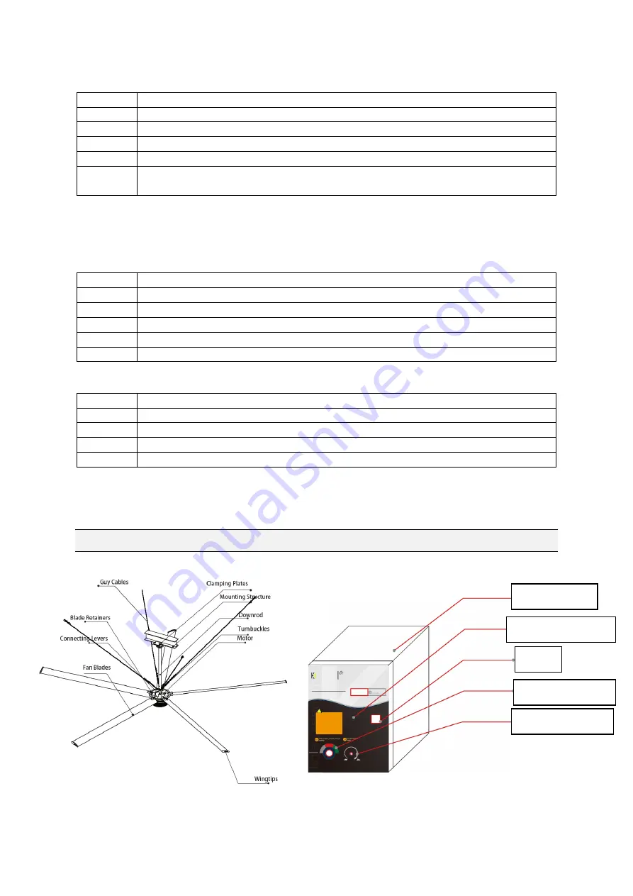
Fan Diagram & Control Panel 


Control Box 

Power Switch 

Speed Control 

Lock 

Display window 

Summary of Contents for Engine

Page 1: ...EURUSIII HVLS FAN INSTALL USER MANUAL NZ Distributor of KaLe Environmental Technology Shanghai Corp Web www kalefans com...

Page 2: ...mmended Safety Gear 4 What is in the packing case 4 Packing List 5 Equipment Tools needed 5 Fan Diagram Control Panel 6 Preparing the Work Site 7 Install Appendix 8 Trouble Shooting and Error Codes 9...

Page 3: ...hot spaces which gives us a hands on understanding of what it takes to find the right solution for you Jet Black Fans Systems was born out of finding a solution for keeping our staff and customers hap...

Page 4: ...on the fan controller ensure isolation of main supply from line inputs at the fan controller board Wait three minutes for capacitors to discharge to safe voltage levels notes the displayer blackness...

Page 5: ...allation Recommended Safety Gear Safety Gear Hard Hat Safety Glasses Work Gloves Steel Tipped Work Shoes IMPORTANT NOTE Persons entering the work zone should always wear a hard hat safety glasses work...

Page 6: ...5mm Nuts Bolts Flat Lock Washers 7 18 M12 X 70mm Nuts Bolts Flat Lock Washers 7 19 M4 X 8mm Screw 3 20 Fan Controller Hardware Set 1 21 Turnbuckles 4 23 Hose clamps 20 Equipment Tools needed Equipment...

Page 7: ...ee above grade General Tools for Mechanical Installation S No Description 1 Standard Socket and ratchet Set 2 Standard Socket and ratchet Set 3 Standard Phillips and Flat Head Screwdriver set 4 Level...

Page 8: ...A scissor lift or other suitable means for lifting the weight of the fan and at least two installation personnel will be required b If using a square tubing arrangement it is recommended to have this...

Page 9: ...e fan installation area must be free of obstructions such as light cables sprinklers or other building structure Blade height At least 3 meters above the floor Fan spacing 4 x fan diameter centre to c...

Page 10: ...iew the VSD drive booklet for further error codes and fixes Non professional staffs do not open the electrical control box Notes Equipment damages due to the improper use are not covered by the warran...

Page 11: ...ng plates Shims and M16 x 55mm hardware as shown in the figure below NOTE The mounting details shown in this section is for I Beam only See Install Appendix for Square Beam and Square Tube Contact Jet...

Page 12: ...nting plate See Figure below 3 3 Using a level gauge check and ensure that the fan assembly is levelled in the X and Y axis and completely tighten the pre tensioned M16 x 140mm 4 Installing Turnbuckle...

Page 13: ...nd and third wire rope clips at 7 5cm 9cm apart from each other Dead end of the guy cable should not extend more than 5cm out from the third wire rope clip Be sure that all the wire rope clips are tig...

Page 14: ...wire thimble to make second Loop Refer to Step 4 1 for detailed instructions of Guy Wire Loop Loosely tighten the guy cable by pulling the dead end of the guy cable Do not use Beam Clamp as shown in i...

Page 15: ...he fan blades with Fan Blade tail attached onto the connecting arms and install the blade retainers and the fan blades with the M10 hardware as shown in the figure NOTES Ensure that all the M12 hardwa...

Page 16: ...register your fan product with Jet Black Fan Systems Diameter 4 9m 5 5m 6 1m 7 3m Weight 106KG 114KG 120KG 135KG Input Voltage 240V 1P 240V 1P 240V 1P 240V 1P KW input 1 8 1 8 1 8 1 8 Full Load Curre...

Page 17: ...d reversion the Engine or Eurus HVLS ceiling fan system starts automatically as the power knob is still at RUN position To prevent motor damage ensure that the power switch is turned to STOP position...

Page 18: ...personnel Maintenance Record Date Check complete by name company Notes Limited Warranty For Jet Black Fan Systems Industrial Engine and EurusIII Series HVLS Ceiling Fans Coverage The Limited Warranty...

Page 19: ...arranty is void if the fan is exported outside of the country to which the original sale was made unless authorized by Jet Black Fan Systems Customers outside NZ and Australia must purchase the fan di...

Page 20: ...pair or replace the defective component and ship it back to the customer If it is determined that the source of component failure is outside of the scope of this warranty then the Customer will be giv...

Reviews: