20
Adjusting the take-up screw nuts on either side
of the conveyor allows belt tracking adjustments
to be made without affecting belt tension.
NOTE: Adjust take-up screw nuts only 1/4 turn
at a time. Then allow time for the belt to react to
the adjustments before proceeding further. Try
to avoid over adjustments.
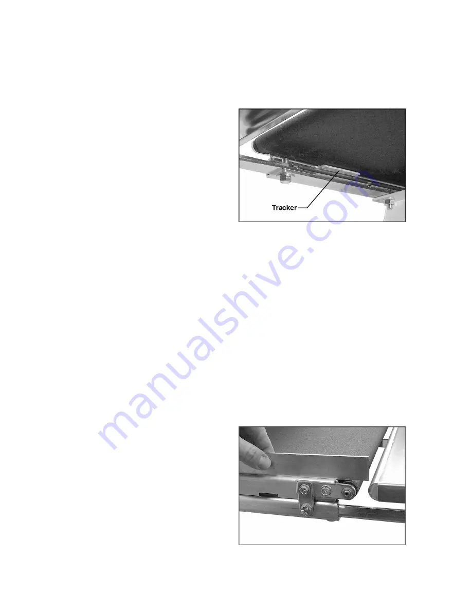
Trackers
The sander comes equipped with “Trackers”,
ceramic guides that reduce the amount of
adjustments needed to keep the conveyor belt
tracked (centered) on the conveyor bed. See
Figure 32. These guides have a magnetic
backing to keep them in place. If a Tracker
wears through, it can be reversed by turning it
over. Page 27 contains more information about
re-setting trackers.
Conveyor Belt Replacement
1. To replace a worn conveyor belt, lower
conveyor table to its lowest position using
the height adjustment handle. Unplug the
machine from the wall receptacle, and
unplug the motor cord from the control box
receptacle.
2. Loosen the conveyor take-up screw nuts
(see Figure 31) to relieve belt tension, and
slide the driven roller fully inward.
3. Remove the four bolts that attach the
conveyor table to the table mounting
brackets. Lift up the conveyor table and
remove it from machine. Avoid tearing the
belt on any edges underneath the conveyor
bed.
4. Install new belt, and re-install conveyor
table. Take care not to damage the
Trackers. Tension and track new belt.
NOTE: If the conveyor belt continually tracks to
one side of the machine, reversing the belt on
the conveyor bed may remedy the problem. To
make sure the conveyor bed is not twisted,
place a level on the conveyor bed. If it is twisted,
see page 11 for instructions on leveling the
machine. If there is still a problem, proceed with
the steps below:
Step 1: Check the conveyor drive roller and the
driven roller to make sure they are parallel to the
surface of the conveyor bed. To do this, first
center the conveyor belt on the bed. Then lay a
straight-edge on the exposed edge of the
conveyor bed on the left (outboard) side,
extending it over the roller. See Figure 33. Note
the distance between the roller and the
straightedge.
Figure 32
Figure 33
Summary of Contents for SandSmart 22-44 Pro
Page 34: ...34 Stand Assembly...
Page 36: ...36 Drum Head Assembly...
Page 38: ...38 Conveyor and Motor Assembly...
Page 41: ...41 Electrical Connections...
Page 42: ...42 NOTES...
Page 43: ...43...


