13
7.9
Coolant flow
Coolant pump must be
submerged before operating to prevent damage
to pump.
The blade guides are fitted with coolant valves.
Coolant is provided to the fittings through
interconnecting tubing, and is dispensed directly
onto saw blade.
Adjust coolant flow valves atop blade guide brackets
to provide desired flow. The flow should be no more
than blade can draw into the workpiece by its
movement through the material.
The coolant flow can be stopped in two ways: Turn
off coolant pump switch on control panel, or close
coolant flow valves.
8.0
Control panel
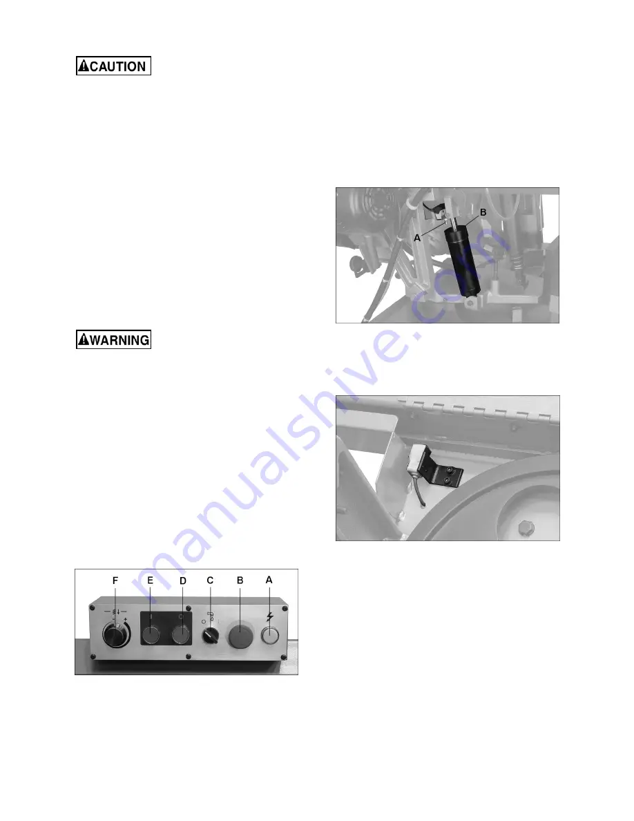
Refer to Figure 8-1.
Power Indicator Light (A)
– illuminates whenever
machine is running.
If bulb is out, light will not be
on but machine may still have power.
Emergency Stop Button (B)
– Press to immediately
stop all machine functions. To restart machine,
rotate button clockwise until it disengages.
Coolant Switch (C)
– Turn arrow to “I” to turn on
coolant flow. Turn arrow to “O” to stop coolant flow.
Stop Button (D)
– Press to stop motor/blade.
Coolant will still flow.
Start Button (E)
– Press to start motor/blade.
Feed Rate Control (F)
– Sets amount of downward
force that is applied to saw blade. The feed rate is
proportional to opening of valve. Increasing valve
opening (counterclockwise) increases feed rate;
decreasing valve opening (clockwise) reduces feed
rate. When set to zero, bow is locked in raised
position.
Figure 8-1: control panel
9.0
Operation
9.1
Automatic shut-off
9.1.1
Cut completion
The machine and any accessories which are wired
into the electrical system are controlled by the start-
stop buttons. Saw will automatically shut off when
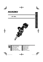
cut is completed. The limit switch (A, Figure 9-1),
contacts top of hydraulic cylinder (B) and
deactivates motor.
Figure 9-1: auto shut-off switch
9.1.2
Blade breakage
If blade breaks during operation, a sensor near drive
wheel will shut off the saw (Figure 9-2).
Figure 9-2: blade break sensor
9.2
Auxiliary coolant hose
The saw is equipped with auxiliary coolant hose and
spray nozzle. This can be used to direct greater
volume of coolant at workpiece, or for washing off
table area.
9.3
Prior to Operation
1. Check that blade tooth direction matches
diagram on blade guard, and blade guides are
properly set.
2. Check gauge to verify proper blade tension.
Make adjustments if needed.
3. Check to see that blade is properly seated on
wheels after applying correct tension.
Summary of Contents for MBS-1018-1
Page 18: ...18 12 1 1 MBS 1018 1 MBS 1018 3 Bow Assembly Exploded View...
Page 22: ...22 12 2 1 MBS 1018 1 MBS 1018 3 Base Assembly Exploded View...
Page 26: ...26 12 3 1 MBS 1018 1 MBS 1018 3 Electrical Box Assembly Exploded View...
Page 29: ...29 13 2 Wiring Diagram for MBS 1018 3...
Page 31: ...31 This page intentionally left blank...
Page 32: ...32 427 New Sanford Road LaVergne Tennessee 37086 Phone 800 274 6848 www jettools com...


