background image

 10

7.0

  Adjustments 

 Disconnect machine from 

power source before making adjustments, 
unless indicated otherwise. 

7.1

  Blade installation and removal 

Refer to Figure 7-1. 


Always wear leather gloves 

when handling blades to avoid injury.


A blade (1in. W x 144in. L) is pre-installed and 
tensioned on saw. To replace blade: 

1.  Disconnect machine from power source. 

2. 

Close 

feed rate knob by turning it clockwise as 

far as it will go, then raise bow a little. 

3. 

Open both wheel covers (A, Figure 7-1) and clean 
out any swarf from wheel areas

4.  Remove blade guards (B, C). 

5. 

Release blade tension by turning blade 

tension 

handwheel (D) counter-clockwise. 

6. 

Remove blade from both wheels and out 

of each 

blade guide. 

7. 

Make sure teeth of new blade 

are pointing in 

direction of travel. If necessary, turn blade 
inside out. 

8.  Position new blade around wheels and through 

upper blade guard (E, Figure 7-1). Slide it into 
the blade guide bearings with back edge of 
blade contacting backup bearing. (see Figure 7-
2). If guide bearing adjustment is needed, see 

sect. 7.3


9.  Lightly increase tension (D) and position blade 

so it rests against shoulder of both wheels. 

10. When blade is properly positioned, place full 

tension upon it (see 

sect. 7.4.1

). 

11.  Reinstall blade guards (B,C). 

12. Jog the On/Off button to ensure blade is 

tracking properly. If tracking adjustment is 
needed, see 

sect. 7.4.2

13.  Close wheel covers and reinstall their screws. 


Figure 7-1 

7.2

  Bracket adjustment 

The blade guide brackets (F, Figure 7-1) must be 
set to just clear the workpiece, but should not 
interfere with workpiece or other saw components 
during bow’s descent. 

Loosen knobs and slide brackets into position. 
Always tighten knobs before operating machine. 
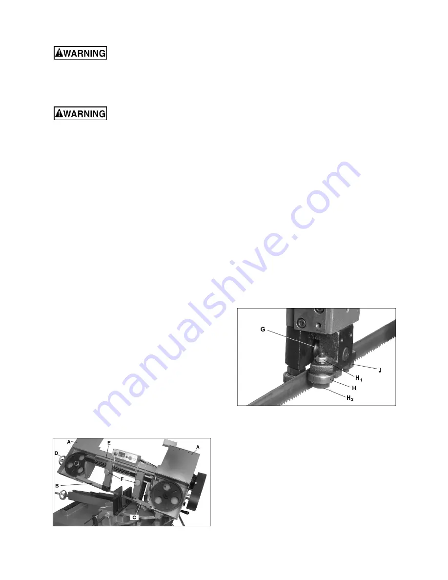
7.3

  Blade guide bearing adjustment 

The back of blade should ride against back-up 
support bearing (G, Figure 7-2) which is positioned 
at an angle to provide greater bearing support, 
eliminating bearing wear and extending blade life. 

The blade should also ride between the two roller 
bearings. The front bearing (H) on left hand blade 
guide is on an eccentric shaft and can be adjusted 
to suit


blade thickness: 

1.  Disconnect machine from power source.  

2.  Loosen nut (H

1

) and turn lower nut (H

2

) to 

position bearing. Retighten nut (H

1

). Do not 

overtighten the bearings against the blade; 
when adjusted properly, the bearings should be 
able to be rotated with your fingers with only 
minor resistance, with the blade stopped. 

3.  After completing above adjustments, loosen set 

screws (J) and adjust both tungsten carbide 
guides against surface of blade. Retighten set 
screws. 

4.  Adjust the right hand tungsten carbide guides in 

the same manner. 


Figure 7-2:  blade guide bearing adjustment 

7.4

  Blade tension and tracking 

Refer to Figure 7-3. 

7.4.1

  Tension 

Blade tension has been set by manufacturer at 
approximately 1800 kg/cm2 (25,000 psi) for the 
supplied blade, but should be verified by the 
operator. Turn handwheel (D, Figure 7-3) clockwise; 
if collar (K) slips out of position, then blade is 
properly tensioned. Continue turning handwheel 
until collar re-engages. NOTE: Simply turn 
handwheel, do not press on it. 

Summary of Contents for MBS-1018-1

Page 1: ...ons and Parts Manual Horizontal Dual Mitering Band Saw Models MBS 1018 1 MBS 1018 3 JET 427 New Sanford Road LaVergne Tennessee 37086 Part No M 413410 Ph 800 274 6848 Edition 2 06 2017 www jettools co...

Page 2: ...or maintenance with the machine unplugged from the power source 14 Remove adjusting keys and wrenches Form a habit of checking to see that keys and adjusting wrenches are removed from the machine bef...

Page 3: ...mmed pieces until blade has stopped 36 Don t use in dangerous environment Don t use power tools in damp or wet location or expose them to rain Keep work area well lighted 37 Use proper extension cord...

Page 4: ...2 Auxiliary coolant hose 13 9 3 Prior to Operation 13 9 4 General operating procedure 14 9 5 Evaluating cutting efficiency 14 9 6 Blade selection 14 9 7 Blade break in procedures 15 10 0 User maintena...

Page 5: ...omments please contact your local supplier or JET JET can also be reached at our web site www jettools com Retain this manual for future reference If the machine transfers ownership the manual should...

Page 6: ...s 50 125 200 275 SFPM 50 125 200 275 SFPM Coolant tank capacity 15 L 4 gal 15 L 4 gal Gearbox oil capacity 850 mL 0 9 qt 850 mL 0 9 qt 90 degrees 60 degrees 45 degrees Tubing Round 10 in 254mm 6 in 15...

Page 7: ...levels and are not necessarily to be seen as safe operating levels As workplace conditions vary this information is intended to allow the user to make a better estimation of the hazards and risks invo...

Page 8: ...bolts with hex nuts through the base flanges as shown in sect 12 2 1 index 280 and 283 4 Place a level on the table surface and check side to side and front to back 5 Adjust leveling screws until mach...

Page 9: ...circuit the reconnection should be made by qualified service personnel and after reconnection the tool should comply with all local codes and ordinances If hardwired Permanently connected tools This t...

Page 10: ...e blade guide brackets F Figure 7 1 must be set to just clear the workpiece but should not interfere with workpiece or other saw components during bow s descent Loosen knobs and slide brackets into po...

Page 11: ...e away from wheel shoulder then immediately turn single hex adjustment screw in opposite direction so that blade stops then moves slowly toward shoulder Keep fingers clear of blade and wheel to avoid...

Page 12: ...components then tighten both handles T Figure 7 6 vise adjustment 7 7 Bow swivel adjustment Refer to Figures 7 7 and 7 8 1 Remove 90 stop pin V 2 Lift up on lever W and push bow to desired angle accor...

Page 13: ...ntrol F Sets amount of downward force that is applied to saw blade The feed rate is proportional to opening of valve Increasing valve opening counterclockwise increases feed rate decreasing valve open...

Page 14: ...ency Is the blade cutting efficiently The best way to determine this is to observe the chips formed by the cutting blade If chip formation is powdery then feed rate is much too light or blade is dull...

Page 15: ...and debris Keep slide areas such as vise ways and T slot slide for bow swiveling and behind scale where blade brackets slide clean and oiled Make sure vise lead screw remains free of cuttings or other...

Page 16: ...ease spring tension Hard spots in workpiece or scale on in workpiece Increase feed pressure hard spots Reduce speed increase feed pressure scale Work hardening of material especially stainless steel I...

Page 17: ...de too coarse for workpiece especially with tubular stock Use blade with fine tooth pitch Blade too fine for workpiece especially with heavier soft material Use blade with coarse tooth pitch Insuffici...

Page 18: ...18 12 1 1 MBS 1018 1 MBS 1018 3 Bow Assembly Exploded View...

Page 19: ...6 Special Washer 1 28 MBS 1018 1 28 Wheel LH 1 29 BB 6306ZZ Bearing 6306ZZ 2 MBS 1018 GBA Gear Box Assembly includes 31 47 50 58 82 1 31 EHB916V 31 Output Shaft 1 32 EHB916V 32 Oil Seal 32 42 7 1 33 B...

Page 20: ...95MFC Motor Fan Cover 1 EHB1018V 95MF Motor Fan 1 EHB1018V 95MJB Motor Junction Box 1 EHB1018VM 95 Motor 2HP 230 460V 3PH 1 EHB1018VM 95MFC Motor Fan Cover 1 EHB1018VM 95MF Motor Fan 1 EHB1018VM 95MJB...

Page 21: ...3 16 x 3 8 2 154 2 F002633 Flat Washer 3 16 2 155 MBS 1018 1 155 Bracket LH 4 156 EHB916V 156 Blade Cover 1 156 1 EHB916V 156 1 Screw 3 16 x 3 8 2 156 2 F002633 Flat Washer 3 16 2 157 MBS1018 1 157 B...

Page 22: ...22 12 2 1 MBS 1018 1 MBS 1018 3 Base Assembly Exploded View...

Page 23: ...216 EHB916V 216 Seal 1 217 EHB916V 217 O Ring 1 218 TS 0561021 Hex Nut 5 16 x18T 2 219 EHB916V 219 Tube Assembly 1 221 EHB916V 221 Tube Fitting 1 222 EHB916V 222 Tube Fitting 1 223 EHB916V 223 Ext Ret...

Page 24: ...rface 1 273 TS 0267071 Socket Set Screw 1 4 20 3 4 6 274 TS 0051051 Hex Cap Screw 5 16 18 1 3 276 MBS 1018 1 276 Seat 1 277 EHB1018VM 277 Movable Block 1 278 EHB916V 278 Spray Gun Set 1 278 1 EHB916V...

Page 25: ...8061 Socket Head Cap Screw 5 16 18 1 2 314 EHB1018VM 314 Fixing Rod For Spring 1 315 TS 0211071 Socket Head Cap Screw 1 2 1 1 2 1 316 EHB1018VM 316 Spring 1 317 EHB1018VM 317 Spring Cover 1 318 EHB101...

Page 26: ...26 12 3 1 MBS 1018 1 MBS 1018 3 Electrical Box Assembly Exploded View...

Page 27: ...otor Cable 1 308 16 MBS1018 1 308 16 Pump Cable 1 308 19 MBS1018 1 308 19 Limit Switch Cable 1 12 3 3 MBS 1018 3 Electrical Box Assembly Parts List Index No Part No Description Size Qty 308 1 EHB1018V...

Page 28: ...8 13 0 Electrical Connections 13 1 Wiring Diagram for MBS 1018 1 K1 K2 contactor LS4 limit switch M1 main motor M2 coolant pump OL1 overload PB1 emergency stop button PB2 PB3 pushbutton TR transformer...

Page 29: ...29 13 2 Wiring Diagram for MBS 1018 3...

Page 30: ...tional action needed JET has Authorized Service Centers located throughout the United States For the name of an Authorized Service Center in your area call 1 800 274 6846 or use the Service Center Loc...

Page 31: ...31 This page intentionally left blank...

Page 32: ...32 427 New Sanford Road LaVergne Tennessee 37086 Phone 800 274 6848 www jettools com...

Reviews: