background image

 20 

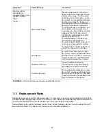
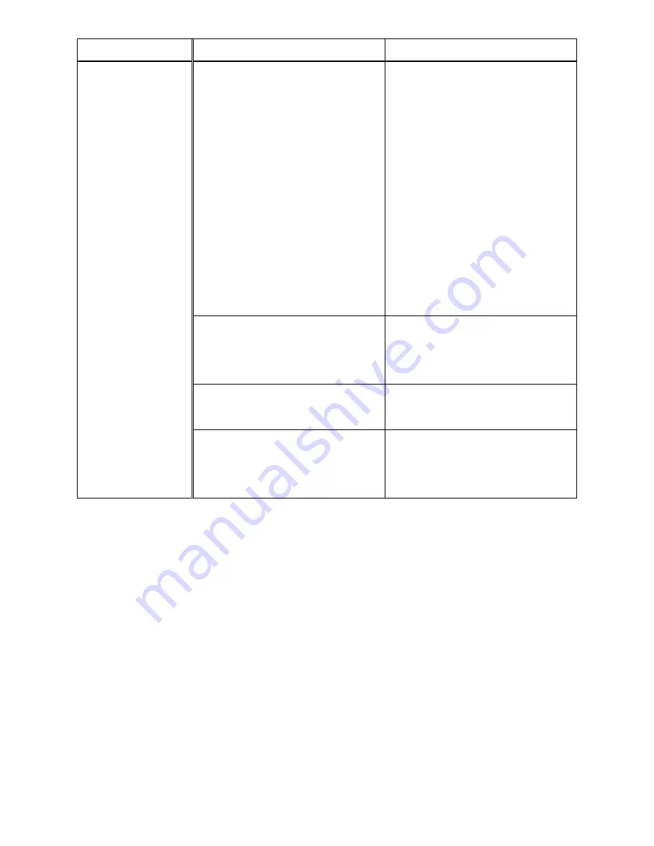
Symptom 

Possible Cause 

Correction * 

Machine will not 
start/restart or 
repeatedly trips circuit 
breaker or blows 
fuses. 

(cont.) 

Motor starter failure. 

 
Examine motor starter for burned or 
failed components. If damage is found, 
replace motor starter. If motor starter 
looks okay but is still suspect, you have 
two options: have a qualified electrician 
test the motor starter for function, or 
purchase a new starter and establish if 
that was the problem on changeout. 
If you have access to a voltmeter, you 
can separate a starter failure from a 
motor failure by first, verifying incoming 
voltage at 230+/-10% and second, 
checking the voltage between starter 
and motor at 230+/-10%.  
If incoming voltage is incorrect, you 
have a power supply problem. 
If voltage between starter and motor is 
incorrect, you have a starter problem.  
If voltage between starter and motor is 
correct, you have a motor problem. 

Motor failure. 

If electric motor is suspect, you have 
two options: Have a qualified electrician 
test the motor for function or remove the 
motor and take it to a qualified electric 
motor repair shop and have it tested. 

Miswiring of the unit. 

Check to confirm all electrical 
connections are correct and properly 
tight. Make any needed corrections. 

On/off switch failure. 

If the on/off switch is suspect, you have 
two options: Have a qualified electrician 
test the switch for function, or purchase 
a new on/off switch and establish if that 
was the problem on changeout. 

WARNING:

  Some corrections may require a qualified electrician. 


11.0

  Replacement Parts 

Replacement parts are listed on the following pages. To order parts or reach our service department, call 1-800-
274-6848 Monday through Friday, 8:00 a.m. to 5:00 p.m. CST. Having the Model Number and Serial Number of 
your machine available when you call will allow us to serve you quickly and accurately. 

Non-proprietary parts, such as fasteners, can be found at local hardware stores, or may be ordered from JET. 
Some parts are shown for reference only, and may not be available individually. 


Summary of Contents for JWP-15B

Page 1: ...s Manual 15 inch Planer Models JWP 15B JWP 15BHH JET 427 New Sanford Road LaVergne Tennessee 37086 Part No M 722150 Ph 800 274 6848 Edition 1 01 2019 www jettools com Copyright 2019 JET JWP 15BHH JWP 15B This pdf document is bookmarked ...

Page 2: ...ine before turning it on 14 Keep safety guards in place at all times when the machine is in use If removed for maintenance purposes use extreme caution and replace the guards immediately after completion of maintenance 15 Check damaged parts Before further use of the machine a guard or other part that is damaged should be carefully checked to determine that it will operate properly and perform its...

Page 3: ...r injury and or possible machine damage This means that if precautions are not heeded it may result in serious or possibly even fatal injury WARNING This product can expose you to chemicals including titanium dioxide which is known to the State of California to cause cancer and lead which is known to the State of California to cause cancer and birth defects or other reproductive harm For more info...

Page 4: ...d control 15 9 0 Maintenance 15 9 1 General maintenance 15 9 2 Lubrication 15 9 2 Belt replacement 16 9 3 Work table parallel to cutterhead 16 9 4 Lubrication points 17 10 0 Troubleshooting JWP 15B 15BHH 18 10 1 Performance problems 18 10 2 Mechanical and electrical problems 19 11 0 Replacement Parts 20 11 1 1 Head Assembly Exploded View 21 11 1 2 Head Assembly Parts List 22 11 2 1 Column Assembly...

Page 5: ...on if used in accordance with the instructions set forth in this document If there are questions or comments please contact your local supplier or JET JET can also be reached at our web site www jettools com Retain this manual for future reference If the machine transfers ownership the manual should accompany it Read and understand the entire contents of this manual before attempting assembly or o...

Page 6: ...um cutting depth 3 16 in 4 7 mm Maximum full width depth of cut 1 8 in 3 1 mm Minimum workpiece length 21 1 2 in 540 mm Head movement per one revolution of handwheel 4 mm Feed rate 16 and 20 FPM Gearbox oil capacity 420 mL Cutterhead and feed rollers Number of cutterhead rows 3 4 Knife type Straight 4 sided knife inserts Number of knives 3 48 Cutterhead speed 5200 RPM Cutterhead diameter 2 6 in 68...

Page 7: ...workplace conditions vary this information is intended to allow the user to make a better estimation of the hazards and risks involved only L length W width H height FPM feet per minute CFM cubic feet per minute n a not applicable The specifications in this manual were current at time of publication but because of our policy of continuous improvement JET reserves the right to change specifications...

Page 8: ...ard not shown Included with model 15B only 2 Steel extension tables not shown 1 Hex wrench 6mm D 1 Knife gauge E 1 Hardware package p n JWP15B HP 1 Socket hd cap screw M5x12 HP1 1 Lock washer M5 HP2 11 Socket hd button screws M6x12 HP3 8 Socket hd cap screws M8x16 HP4 Included with model 15BHH only 2 Cast iron extension tables not shown 2 Star point screwdrivers F 5 Knife inserts G 10 Knife insert...

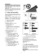
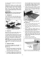
Page 9: ...th steel tables The JWP 15BHH is shipped with cast iron tables JWP 15B only 1 Mount the steel extensions to the main table using the screws provided HP4 Figure 8 9 The bottom screw is used as a stop The extension table pivots on the top screw 2 The extension tables must be leveled with the main table A straight steel bar is ideal for this but a carefully jointed board may also be used Place the st...

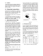
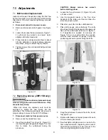
Page 10: ...ive terminal Check with a qualified electrician or service personnel if the grounding instructions are not completely understood or if in doubt as to whether the tool is properly grounded Failure to comply may cause serious or fatal injury Use only 3 wire extension cords that have 3 prong grounding plugs and 3 pole receptacles that accept the tool s plug Repair or replace damaged or worn cord imme...

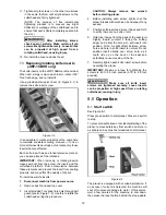
Page 11: ...t machine from power source 2 Remove dust hood and top cover 3 Insert the provided Torx driver C Figure 5 1 into hole through belt guard B Figure 7 2 Use this to rotate the cutterhead during the procedure CAUTION Always remove hex wrench before starting planer 4 Loosen the five gib screws C Figure 7 2 with a 12mm wrench 5 Use the magnetic inserts in the Torx drive handle to lift the knife out of t...

Page 12: ... dust hood and top cover 3 Insert provided Torx driver into hole through belt guard see B Figure 7 2 Use this to rotate the cutterhead during the procedure CAUTION Always remove hex wrench before starting planer 4 Before installing each screw lightly coat the screw threads with machine oil and wipe off any excess 5 Position knife insert and move it back and forth to verify there are no burrs or di...

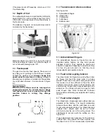
Page 13: ... 8 4 8 5 Anti kickback fingers The anti kickback fingers A Figure 8 4 are an important safety feature as they help prevent kickback of stock They operate by gravity and should be inspected frequently to make sure they are free of gum and pitch so that they move independently and operate correctly 8 6 Feed rollers spring tension The infeed roller B Figure 8 4 and outfeed roller E Figure 8 4 feed th...

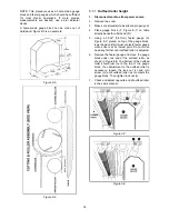
Page 14: ...h cutterhead D 5 Using a 0 032 0 81mm feeler gauge G Figure 8 7 placed on top of the gauge block lower head until knife just contacts feeler gauge when knife is at its lowest point Do not move head any farther until outfeed roller is adjusted 6 Remove the feeler gauge and move the gauge block under one end of the outfeed roller as shown in Figure 8 8 The bottom of the outfeed roller should just to...

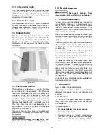
Page 15: ...9 1 General maintenance Periodic or regular inspections are required to ensure that the machine is in proper adjustment that all screws are tight that belt is in good condition that dust has not accumulated in the electrical enclosures and that there are no worn or loose electrical connections Buildup of sawdust and other debris can cause your machine to plane inaccurately Periodic cleaning is not...

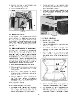
Page 16: ...e should be the same at both ends 4 If the gap difference is greater than 0 004 and less than 0 016 perform the adjustment procedure in sect 9 3 1 If the gap is greater than 0 016 use procedure in sect 9 3 2 9 3 1 Fine adjustment For gap difference 0 004 to 0 016 inches 1 On the side of the table that needs correcting locate the two socket head cap screws for each column Figure 9 2 Loosen both scr...

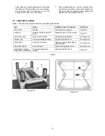
Page 17: ...m Action Suitable Types of Lubricant Reference Drive chain Monthly General purpose grease Figure 9 1 Gear box Drain and refill every 2 500 hours Standard gear oil 70 90 weight Figure 9 1 Lead screw x4 Once every 3 months General purpose grease 3 Figure 9 4 Column x4 Clean and lubricate weekly Light coat of SAE 30 oil 4 Figure 9 4 Table chain Every 4 to 6 months Grease or good quality bicycle chain...

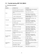
Page 18: ...ing against the grain Cut along the grain where possible Dull knives or knife inserts 15B Sharpen or replace knives 15BHH Rotate or replace inserts Rough raised grain Dull knives or knife inserts 15B Sharpen or replace knives 15BHH Rotate or replace inserts Too heavy a cut Adjust proper depth of cut Planing wood with high moisture content Remove moisture by drying or use different stock Rounded gl...

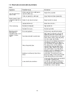
Page 19: ...ilt into the motor starter it takes time for the machine to cool down before restart Allow unit to adequately cool then press reset button Planer frequently trips One cause of overloading trips which is not electrical in nature is too heavy a cut The solution is to take a lighter cut If too deep a cut is not the problem check for other electrical items dust collectors lights heaters etc being used...

Page 20: ...ic motor is suspect you have two options Have a qualified electrician test the motor for function or remove the motor and take it to a qualified electric motor repair shop and have it tested Miswiring of the unit Check to confirm all electrical connections are correct and properly tight Make any needed corrections On off switch failure If the on off switch is suspect you have two options Have a qu...

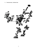
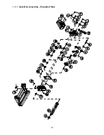
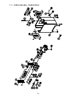
Page 21: ...21 11 1 1 Head Assembly Exploded View ...

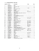
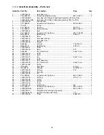
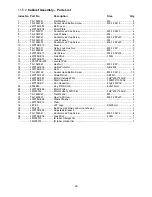
Page 22: ...22 Socket Head Button Screw M6 1 0Px12 15 24 TS 1503051 Socket Head Cap Screw M6 1 0Px20 8 25 TS 1482031 Hex Cap Screw M6 1 0Px16 1 26 TS 1503061 Socket Head Cap Screw M6 1 0Px25 2 27 TS 1550041 Flat Washer M6 6 28 TS 1523081 Set Screw M6 1 0Px30 1 29 TS 1541021 Nylon Lock Hex Nut M6 1 0P 1 33 TS 1503041 Socket Head Cap Screw M6 1 0Px16 4 34 BB 6204VV Ball Bearing 6204 VV 1 35 JWP15B 135 Straight ...

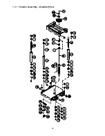
Page 23: ...23 11 2 1 Column Assembly Exploded View ...

Page 24: ...achine Screw M3 0 5Px4 2 14 JPS10TS SHA Handwheel Assembly 1 JPS10TS 168 Handwheel not shown 1 JWTS10 146 Handle not Shown 1 JWTS10 145 Handle Cap not shown 1 JWTS10 147 Shaft not shown 1 F011903 Wave Washer not shown WW 8 1 15 TS 1502031 Socket Head Cap Screw M5 0 8Px12 1 16 TS 1525021 Set Screw M10 1 5Px12 8 17 JWP15H 203 Column Driven 3 18 JWP15H 205 Lead Screw Driven 3 19 JWP16OS 129 Cap 3 20 ...

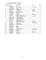
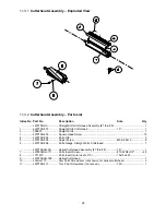
Page 25: ...303 Square Head Screw 15 4 JWP15B 304 Knife Gib 3 5 JWP15B 305 Adjust Screw M5 0 8Px12 6 6 JWP15B 306 Knife Gauge Straight Knife Cutterhead 1 JWP15BHH CA Helical Cutterhead Assembly 7 thru 9 15 1 7 JWP208HH 111 Knife Insert Screw 10 32NFx1 2 48 8 1791212 Knife Insert sold in set of 10 15x15x2 5t 9 JWP15BHH 309 Helical Cutterhead 1 10 JJ6HH 113 Star Point Screwdriver not shown for helical cutterhea...

Page 26: ...26 11 4 1 Gear Box Assembly Exploded View ...

Page 27: ... 1 19 6284843 Oil Seal TC28 40 8 1 20 BB 6201VV Ball Bearing 6201 VV 5 21 JWP15B 421 Shaft 1 22 JWP15B 422 Gear 52T 1 23 6292768 Key Dbl Rd Hd 5x5x12 mm 1 24 JWP15H 314 Shaft 1 25 JWP15H 312 Gear 1 26 JWP15H 313 Key 5x5x10 mm 1 27 JWP15H 323 Shaft 1 28 JWP15H 317 Gear Assembly 1 29 JWP15H 320 Key Dbl Rd Hd 6x6x40 mm 1 30 JWP15H 322 Spring 1 31 SB 6MM Steel Ball Φ 6mm 1 32 OS 25476 Oil Seal SC25 47...

Page 28: ...28 11 5 1 Cabinet Assembly Exploded View ...

Page 29: ... Leveler Pad 4 17 TS 1540061 Hex Nut M8 1 25P 4 18 JWP15B 518 Cable Protector NB 2430 1 19 JWP15B 519 Door 2 20 TS 2246122 Socket Head Button Screw M6 1 0Px12 10 21 JWP15B 707 Strain Relief SB7R 3 2 22 JWP15B 522 Motor includes 25 3HP 230V 60HZ 1 JWP15B SC Start Capacitor 300MFD 125VAC 1 JWP15B RC Run Capacitor 60 F 250VAC 1 23 5509069 Key Dbl Rd Hd 6x6x18mm 1 24 JWP15B 524 Motor Pulley 1 25 LM000...

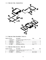
Page 30: ... Support 4 3 JWP15B 603 Torx Head Screw M6 1 0Px12 8 5 JWP15B 605 Main Table 1 6 TS 1504031 Socket Head Cap Screw M8 1 25Px16 8 TS 152707 Allen Wrench not shown 6mm 1 11 6 3 Extension Table Cast Iron Parts List Index No Part No Description Size Qty JWP15BHH CETA Cast Iron Extension Table Assembly 7 thru 9 7 JWP15BHH 607 Cast Iron Extension Table 2 8 TS 1524051 Set Screw M8 1 25Px20 6 9 TS 1490041 ...

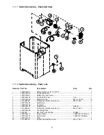
Page 31: ... 703 Machine Screw M4 1 41Px10 10 4 TS 2284082 Phillips Pan Hd Machine Screw M4 0 7Px8 2 5 JWP15B 705 Switch Box 1 6 JWP15B 706 Contactor 1 7 JWP15B 707 Strain Relief SB7R 3 3 8 TS 1532032 Phillips Pan Hd Machine Screw M4 0 7Px10 2 9 JWP15B 709 Grounding Plate 1 10 F001995 Ext Tooth Lock Washer 8 M4 2 11 JWP15B 711 Power Cable 14AWG 3C 3100mm 1 12 JWP15B 712 Motor Cable 14AWG 3C 850mm 1 13 JWP15B ...

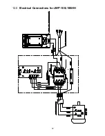
Page 32: ...32 12 0 Electrical Connections for JWP 15B 15BHH ...

Page 33: ...itional action needed JET has Authorized Service Centers located throughout the United States For the name of an Authorized Service Center in your area call 1 800 274 6846 or use the Service Center Locator on the JET website More Information JET is constantly adding new products For complete up to date product information check with your local distributor or visit the JET website How State Law App...

Page 34: ...34 This page intentionally left blank ...

Page 35: ...35 This page intentionally left blank ...

Page 36: ...36 427 New Sanford Road LaVergne Tennessee 37086 Phone 800 274 6848 www jettools com ...

Reviews: