15
8.7.2
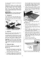
Infeed roller height
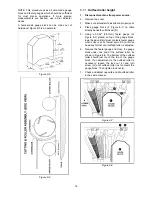
Use the identical procedure for checking the infeed
roller as you did for the outfeed roller. Use the 0.032"
(0.81mm) feeler gauge atop the gauge block. If
adjustment is necessary, use the lock nut and screw
on each end of infeed roller.
8.7.3
Chipbreaker height
The chipbreaker breaks off the larger chips before
the stock reaches the cutterhead. A spring allows it
to adjust automatically for contact with workpiece.
No further adjustments should be needed.
8.8
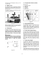
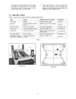
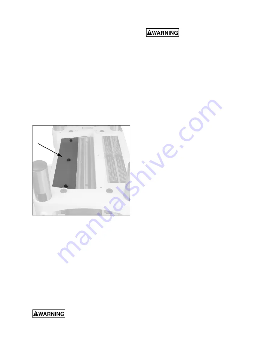
Chip deflector
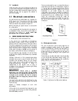
The chip deflector (Figure 8-9) keeps wood chips
from falling into the outfeed roller. The deflector
should be set approximately 1/16" to 1/8” from the
tip of the knives. Make sure deflector is oriented so
that bevel on its front edge matches the shape of the
cutterhead.
Figure 8-9
8.9
Feed speed control
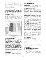
Your machine is equipped with a straight, serrated
infeed roller and a rubber outfeed roller. When the
feed rollers are engaged, they turn to feed the stock.
The feed rollers slow automatically when the
machine is under heavy load for best planing in all
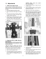
conditions. The feed rollers are driven by chains and
sprockets (see Figure 9-1) which take power directly
from the cutterhead through the oil bath gear box.
The drive chain does not need tensioning, as a
spring-loaded tension device (Figure 9-1) maintains
proper tension at all times.
To access chain and sprockets, use provided star-
point wrench to remove two screws and remove
chain guard.
Always re-install cover over
chain and sprockets before operating planer.
9.0
Maintenance
Disconnect machine from
power source before performing maintenance.
9.1
General maintenance
Periodic or regular inspections are required to
ensure that the machine is in proper adjustment,
that all screws are tight, that belt is in good
condition, that dust has not accumulated in the
electrical enclosures, and that there are no worn or
loose electrical connections.
Buildup of sawdust and other debris can cause your
machine to plane inaccurately. Periodic cleaning is
not only recommended but mandatory for accurate
planing.
Close-fitting parts, such as the cutterhead slot and
gibs, should be cleaned with a cloth or brush and
non-flammable solvent, and freed from clinging
foreign matter.
Remove resin and other accumulations from feed
rollers and table with a soft rag or stiff brush.
Periodically check the chains for proper tension and
adjust accordingly if required.
The table should be kept clean and free of rust.
Some users prefer a paste wax on exposed steel
and cast iron surfaces. The wax provides a layer of
protection as well as reducing friction between
lumber and the table, making cuts faster and
smoother. Avoid any wax that contains silicone or
other synthetic ingredients; these materials can find
their way into lumber and make staining and
finishing difficult.
Alternatively, aerosol protectants are available from
most hardware and tool stores.
9.2
Lubrication
Refer to Table 3 for lubrication points.
The bearings on the cutterhead are factory
lubricated and sealed for life; no lubrication is
required.
9.2.1
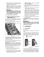
Gearbox
The lubricant in the gear box should be replaced
every 2,500 hours. Multi-purpose gear box lubricant
will be suitable.
To replace lubricant:
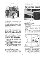
1. Disconnect planer from power source.
2. Remove gear box cover.
3. Remove drain plug (A, Figure 9-1), and remove
filler cap (B). Drain the used oil thoroughly.
Follow local codes for proper disposal of used
oil.
Summary of Contents for JWP-15B
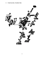
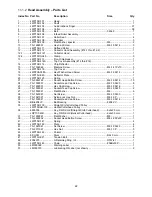
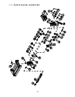
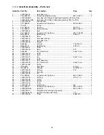
Page 21: ...21 11 1 1 Head Assembly Exploded View ...
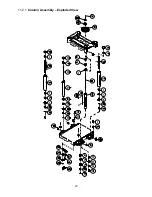
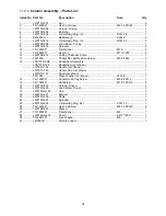
Page 23: ...23 11 2 1 Column Assembly Exploded View ...
Page 26: ...26 11 4 1 Gear Box Assembly Exploded View ...
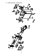
Page 28: ...28 11 5 1 Cabinet Assembly Exploded View ...
Page 32: ...32 12 0 Electrical Connections for JWP 15B 15BHH ...
Page 34: ...34 This page intentionally left blank ...
Page 35: ...35 This page intentionally left blank ...
Page 36: ...36 427 New Sanford Road LaVergne Tennessee 37086 Phone 800 274 6848 www jettools com ...


