


14
Figure 17
8.12
Face plate: Installing/removing
1. Disconnect lathe from power source.
2. Mount the face plate to your workpiece.
3. Engage spindle lock pin.
4. Install face plate onto threads of headstock
spindle and rotate clockwise as far as it will go.
5. Face plate is now ready for turning.
6. To
remove
the face plate, engage spindle lock,
and turn face plate counterclockwise with face
plate wrench.
8.13
Checking center alignment
When the headstock is returned from outboard
position, the alignment between centers should be
checked.
1. Lock the headstock in normal spindle turning
position.
2. Slide the tailstock toward the headstock until
the centers almost touch (see Figure 18). Lock
the tailstock in position.
3. View the center points from top and side to
make sure they align.
4. If the centers do not align, unlock the headstock
and pivot it slightly. There should be enough
“play” in the headstock to adjust for this
alignment. Lock the headstock when finished.
Figure 18
9.0
Operating controls
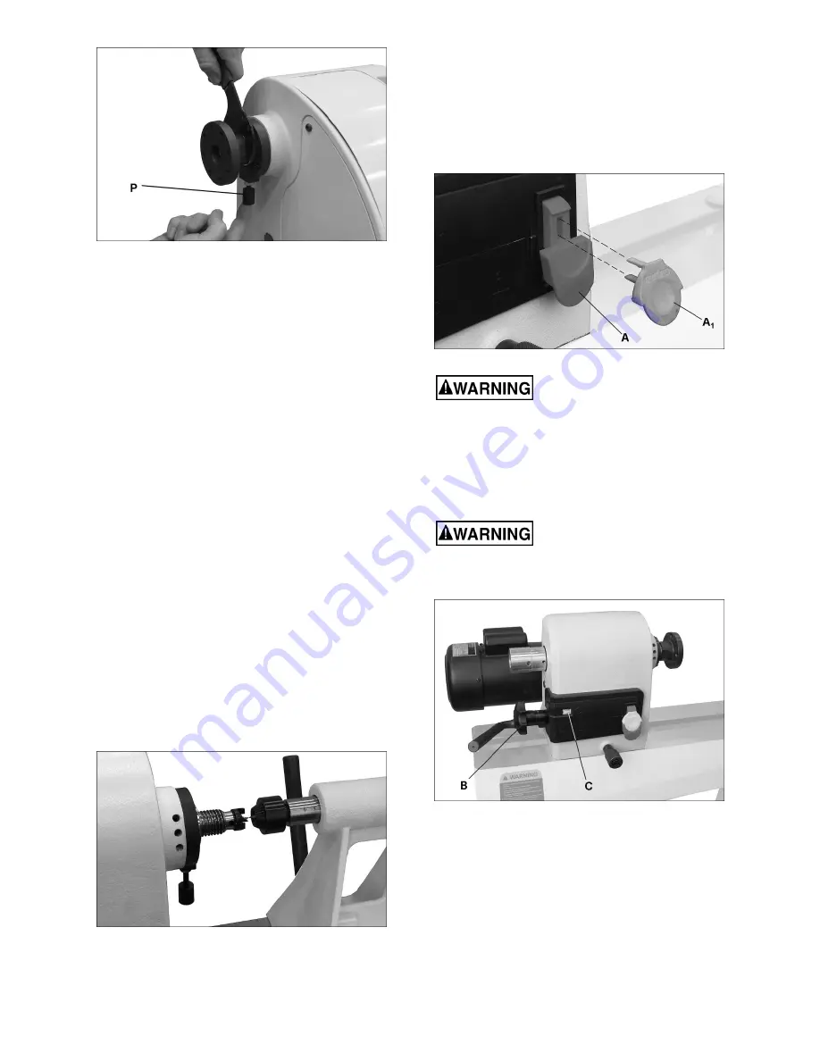
Refer to Figure 19.
On/off switch
(A): Pull to start lathe, push to stop.
The safety key (A
1
) can be removed to prevent
unauthorized use of lathe. The safety key must be
inserted to restart the lathe.
Figure 19
If a power outage should occur
during operation, the lathe will immediately
restart when power is resumed if the start switch
is still engaged. Push switch immediately to OFF
position in the event of a power outage.
Speed control handle:
Rotate handle (B, Figure
20) to set speed, which is displayed as RPM
(revolutions per minute) in the adjoining window (C).
Do not start lathe at maximum
speed when a workpiece is mounted in the lathe.
Start at lower speed and gradually increase to
desired speed.
Figure 20
The JWL-1440VS contains a Reeves or “split-
pulley” system.
As speed is increased, via the speed change
handle, the
spindle pulley
widens and the belt drops
down to the smaller diameter between the pulley
halves. Conversely, the
motor pulley,
which is
spring-loaded so that it adjusts automatically to the
movement of the spindle pulley, gets narrower,
drawing the belt outward toward the larger diameter.


