10
8.3
Site preparation
The mill must be placed on an even surface and
bolted to the floor. Anchor bolts of sufficient size
and length must be fastened to the floor according
to the mill’s footprint. See the site installation
diagram in Figure 1.
8.4
Lifting the mill
Finish removing the sides of the crate. Leave mill
bolted to pallet until ready to move to its final
location.
The preferred method for lifting mill is with a hook
through the hoisting ring screwed into the tapped
hole atop the ram. Steady mill to prevent it from
spinning.
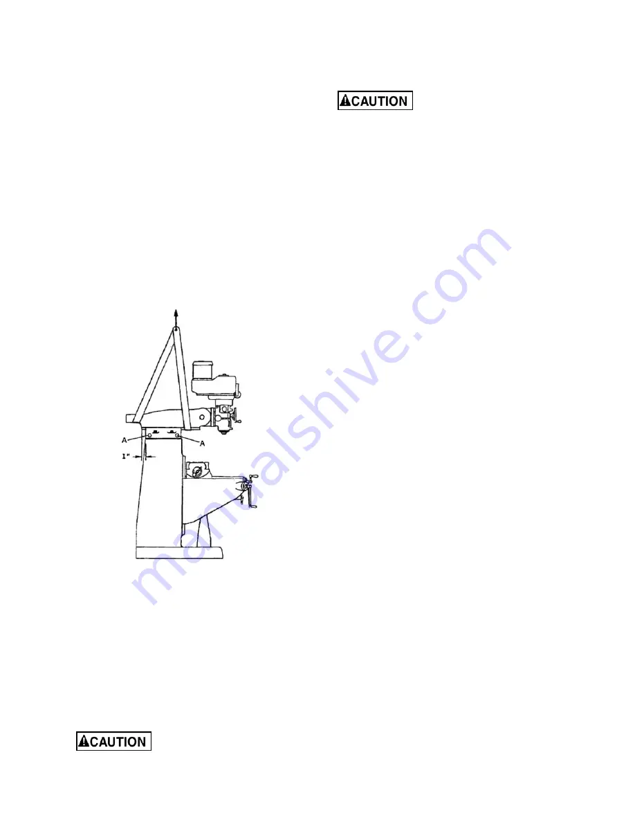
An alternative method for lifting mill is with a sling.
Follow diagram in Figure 1 for proper position of
sling under ram. Note position of ram and that table
has been moved against column. Tighten ram
locking bolts (A, Figure 4) before lifting.
Figure 4: sling location
Carefully lift mill and move to a position over the
anchor bolts. Lower mill over anchor bolts and
check for level, with a machinist’s level placed on
the table. Mill must be level back to front and side
to side. Shim if necessary, but remember that mill
must be supported equally at all four corners.
Check for level before tightening anchor bolt nuts,
and check again after tightening them.
It is advisable when placing the mill on a concrete
floor to use grout (thin mortar) to correct any
unevenness in the concrete and provide a solid
foundation at all points.
Mill must be supported equally
under all four corners. Failure to comply may
cause the column to twist and put a bind in the
ways.
8.5
Completing assembly
Before attempting to raise mill
head, familiarize yourself with instructions in
section 12.1
, for procedures to safely raise and
set up the mill head.
1. Loosen four hexagonal nuts (see A, Figure 9)
about 1/4 turn each counterclockwise, just
enough to allow rotation of head.
2. Apply upward pressure on motor by hand to
relieve pressure on worm mechanism, and use
supplied wrench to turn worm nut and raise
head to upright position.
3. Slightly tighten nuts (A, Figure 9); not torqued,
just snug.
Before operating mill, follow
procedures in section 12.1 to verify angle
settings and properly tighten the four nuts.
4. Use mineral spirits, kerosene or other cleaning
solvent, to remove all rust-proofing from where
it may have been applied. This is important;
moving the table or any other components
before removing rust proofing will only put rust
proofing where you don’t want it. (Do not use
gasoline, paint thinner, or lacquer thinner;
these will damage painted surfaces.)
5. Lubricate exposed ways
(see sect. 13.0)
, then
move each unit (table and ram) to the opposite
limit stop, and clean and lubricate the newly
exposed ways. Loosen bolts to unlock ram and
move it forward and backward to the full length
in order to clean and lubricate.
6. Cover all machined surfaces with a film of light
machine tool oil to inhibit rust.
Some of the following steps may have already
been performed on the machine. If so, ignore the
instructions related to those particular steps.
Otherwise, perform them in the order listed. Refer
to Figures 2 and 5 to help locate items.
7. Install the table traverse and cross-feed
handles on their respective shafts. Tighten
each handle using a wrench on the flats.
8. Remove any rust proofing from drawbar. Install
drawbar with its washer into spindle center
through top of head assembly. When installing
tool into spindle, lock spindle and tighten
drawbar using provided wrench.
9. Slide the fine feed handwheel over the hub
and push it back until its roll pin engages hole
in hub, and handwheel is flush with hub
surface.
10. Place coarse feed handle on feed shaft,
aligning roll pin with a hole. Tap handle lightly
until it is flush against hub surface.
Summary of Contents for JTM-1
Page 6: ...6 5 0 JTM 1 JTM 2 installation layout Figure 1 ...
Page 21: ...21 15 1 1 Upper Head Assembly Exploded View ...
Page 24: ...24 15 2 1 Head Assembly Exploded View ...
Page 28: ...28 15 3 1 Base Assembly Exploded View ...
Page 33: ...33 16 0 Electrical Connections ...
Page 34: ...34 This page intentionally left blank ...
Page 35: ...35 This page intentionally left blank ...
Page 36: ...36 427 New Sanford Road LaVergne Tennessee 37086 Phone 800 274 6848 www jettools com ...


