background image

12

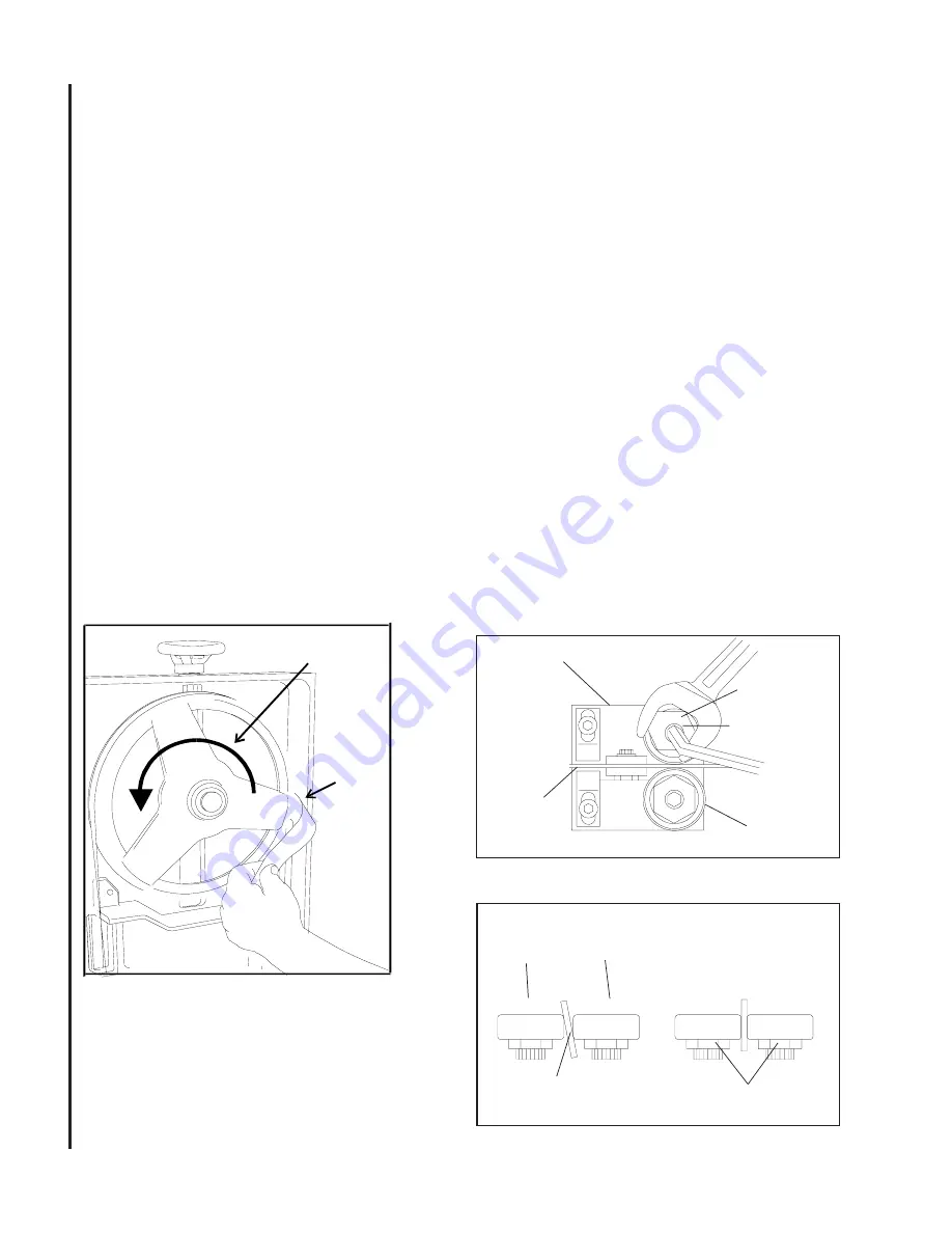
the wheel shoulder.  Put a 6-inch length of paper
between the blade and the wheel as shown in figure
11.  The paper should not be cut as it passes be-
tween the wheel shoulder and the blade.

9.  Turn the single hex adjustment screw a small amount.

Repeat the insertion of the paper between the wheel
shoulder and the blade until the paper is cut in two
pieces.

NOTE:

  You may have to repeat the check with the

paper several times before the blade and the shoulder
cuts the paper into two pieces.  Do not hurry the ad-
justment.  Patience and accuracy here will pay off with
better, more accurate, quieter cutting and much longer
machine and blade life.

10.  When the paper is cut, turn the hex adjustment

screw slightly in the counterclockwise direction.  This
assures that the blade is not touching the shoulder
of the wheel.

11. Shut off the saw.
12. Hold the hex adjustment screws with a wrench and

tighten the center locking screws.  Make sure the
hex adjustment screws do not move while tightening
the center screws.

13. Install the two blade guide bearing brackets.  Posi-

tion the guides so the bearings just touch the blade.

14. Install the left blade guard.
15. Close the saw head cover. Tighten all four knobs.

should rarely require adjustment.  When adjustment is
required, adjust immediately.  Failure to maintain proper
blade adjustment may cause serious blade damage or
inaccurate cuts.

It is always better to try a new blade when cutting

performance is poor. If performance remains poor af-
ter changing the blade, make the necessary adjust-
ments.

If a new blade does not correct the problem, check

the blade guides for proper spacing.  For most effi-
cient operation and maximum accuracy, provide 0.001
inch clearance between the blade and the guide bear-
ings. The bearings will still turn freely with this clear-
ance. If the clearance is incorrect, the blade may track
off the drive wheel.

CAUTION:  

CHECK THE BLADE TO MAKE SURE THE

WELDED SECTION IS THE SAME THICKNESS AS
THE REST OF THE BLADE.  IF THE BLADE IS
THICKER AT THE WELD, THE GUIDE BEARINGS MAY
BE DAMAGED.

If required, adjust the guide bearings as follows:
1.  The inner guide bearing is mounted on a concen-

tric bushing and can not be adjusted.

2.  The outer guide bearing (closest to the operator) is

mounted on an eccentric bushing and can be ad-
justed.

3.  Hold the bushing with a 3/4-inch wrench and loosen

Figure 13: Blade -to-bearing orientation

Figure 12: Adjustment of guide bearings

INCORRECT                             CORRECT

Outer

Roller

Inner

Roller

Blade

Locking

Screw

Guide Bracket

Eccentric

Bushing

Locking

Screw

Blade

Outer Roller

(Blade Guide Roller)

Figure 11: Checking blade-to-wheel clearance
using paper strips

Motor "ON"

Upper Wheel

Rotating

Put Strip

Between

Wheel

and

Blade

Blade Guide Bearing

Adjustment

Proper adjustment of the blade guide bearings is

critical to efficient operation of the cut-off saw.  The
blade guide bearings are adjusted at the Factory.  They

Summary of Contents for J-7040

Page 1: ...nch x 16 Inch Horizontal Band Saw Models J 7020 J 7040 WHM TOOL GROUP Inc 427 New Sanford Road LaVergne Tennessee 30786 Part No M 414472 Ph 800 274 6848 Revision A2 04 09 www wmhtoolgroup com Copyrigh...

Page 2: ...In the event you choose to have the product returned you will be responsible for the shipping and handling costs of the return HOW STATE LAW APPLIES This warranty gives you specific legal rights you...

Page 3: ...xture and Quantity 11 Adjustments 11 Blade TrackingAdjustment 11 Factory or Field Procedure 11 Blade Guide BearingAdjustment 12 Test Cutting to Verify Adjustment Accuracy 13 Adjustment of the Limit Sw...

Page 4: ...2 H P 3 phase 220 440V Blade Size 1 x 035 x 135 Blade Guides Adjustable 6 point contact combination bearing and carbide Blade Wheels 14 diameter cast iron Dimensions Length 79 Width 31 Height 41 Ship...

Page 5: ...when practical It is safer than using your hands and it frees both hands to operate the machine 12 Never brush away chips while the machine is in operation 13 Keep work area clean Cluttered areas inv...

Page 6: ...e 2 All doors shall be closed all panels replaced and other safety guards in place prior to the machine being started or operated 3 Be sure that the blade is not in contact with the workpiece when the...

Page 7: ...ne has been discon nected see figure 4 6 The rate at which the saw head moves downward is controlled by a hydraulic feed rate control located on the top rear of the saw head see figure 3 7 A coolant p...

Page 8: ...ade Efficiency for more information on cutting efficiency Figure 3 Controls Saw Head Lift Handle Control Box Blade Tensioning Hand Wheel Vise Clamping Hand Wheel Blade Guide Supports Drive Motor Blade...

Page 9: ...at its most efficient rate and allow the saw to complete the cut see Evaluating Blade Effi ciency The blade is now considered ready for regular service Work Setup Securing the Workpiece for Square Cut...

Page 10: ...op is used to set up the saw for making multiple cuts of the same length see figure 8 Install and adjust the work stop as follows 1 Insert the end of the stop rod in the hole in the front right side o...

Page 11: ...tion To adjust the blade tracking refer to the following procedures Blade Tracking Adjustment Blade tracking has been tested at the factory Ad justment is rarely required when the blade is used prop e...

Page 12: ...e damage or inaccurate cuts It is always better to try a new blade when cutting performance is poor If performance remains poor af ter changing the blade make the necessary adjust ments If a new blade...

Page 13: ...sition the bearing by turning the bushing Set the clearance at approximately 0 001 inch The blade should be in a vertical position between the bearings See figure 13 5 Tighten the center locking screw...

Page 14: ...the saw at low speed and observe the track ing of the blade If tracking needs to be adjusted refer to Blade Tracking Adjustment 7 Adjust the bearings on the upper edge of the blade until they just con...

Page 15: ...spring pivot post Adjust the tension as required 3 Tighten the two nuts against the pivot post 4 The saw can now be returned to service Replacing the Drive Wheel 1 Remove the blade see Changing Blade...

Page 16: ...support but cannot touch the bottom surface of it when the sawblade is cutting a workpiece Replacement of the Wire Brush 1 Loosen four knobs securing the blade cover Lift the cover and swing it backwa...

Page 17: ...saw is disconnected from the power source orthatthefuseshavebeenremovedorbreak ers tripped in the circuit in which the saw will be connected Make sure you put a warning placard on the fuse or circuit...

Page 18: ...18 Figure 24 Model 7040 cut off saw wiring diagram Figure 25 Connection diagram for 3ph motor...

Page 19: ...o high for feed pres sure 2 Blade is too coarse Suggested remedy 1 Clamp work securely 2 Check Machinist s Handbook for speed feed appropriate for the ma terial being cut 3 Check Machinist s Handbook...

Page 20: ...pitch too coarse for workpiece 2 Feed too slow feed too fast 3 Workpiece vibrating 4 Gullets loading up with chips 1 Blade tension too high 2 Drive belt tension too high 3 Blade too coarse for workpie...

Page 21: ...21 Exploded View Base...

Page 22: ...et 1 ITEM PART NO NO DESCRIPTION QTY 1 J 5712251 Foot Left 1 2 J 5712261 Foot Right 1 3 J 5712271 Coolant Reservoir 1 3 1 5519485 Stopper PT 3 8 1 4 Coolant Pump 1 J 5712281 115 220 1 Phase J 5712921A...

Page 23: ...0 J 5713021Electrical Cabinet Door 1 70 1 5519499 Knob 1 70 2 5519500 Plane 1 71 Overload 1 5507542 Model J 7020 115V 1 ph 5713031 Model J 7020 220V 1 ph 5512660 Model J 7040 220V 3 ph 5712661 Model J...

Page 24: ...5713331 Electric Lamp 1 202 5713341 Start Switch 1 203 5713351 Stop Switch 1 204 5713361 Down Switch 1 205 5713371 E M valve complete 1 215 5712301 Hex Hd Screw 2 216 5712401 Flat Washer 16 217 571250...

Page 25: ...25 Exploded View Head...

Page 26: ...713851A Right Blade Guide Brkt 2 124 1 5519684 Tube 2 Parts List Head ITEM PART NO NO DESCRIPTION QTY ITEM PART NO NO DESCRIPTION QTY 79 5713381 Screw 1 4 x 3 8 4 80 J 5713391 Blade Wheel Cover 1 80 1...

Page 27: ...714141 Hose Clamp 2 151 5713651 Spring Washer 1 4 4 152 5714161 Screw 1 4 x 1 2 4 153 5628371 Spring Washer 1 2 4 154 5714181 Gib 2 155 5714191 Screw 1 2 x 3 4 1 156 5714211 Screw M8 x 20 4 156 1 5519...

Page 28: ...12881 Spring Washer 1 2 4 232 5517141 Eccentric Shaft Bushing 2 233 5517140 Center Shaft Bushing 2 234 5713861 Ball Bearing 6201ZZ 8 235 5713761 Washer 1 2 4 236 5519696 Arm Stop 1 236 1 5711091 Nut 1...

Page 29: ...29...

Page 30: ...30...

Page 31: ...31...

Page 32: ...32 WMH Tool Group Inc 427 New Sanford Road LaVergne Tennessee 30786 Ph 800 274 6848 www wmhtoolgroup com...

Reviews: