Jet IBGM-8VS Operating Instructions And Parts Manual Download Page 8


8

5.0

  Setup and assembly 

5.1

  Unpacking  

Separate all parts from the packing material. Check 
each part against 

sect. 5.2,


Carton contents,

 and 

make certain that all items are accounted for. 
(Check grinder to verify if any parts have been pre-
mounted.) Notify your dealer or JET if parts are 
missing or there is shipping damage. Do not 
discard any packing material until grinder is 
assembled and operating properly.  
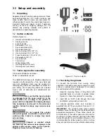
5.2

  Carton contents 

Refer to Figure 5-1.  

1 Grinder 

with 

Multitool 

(not shown)


1 Spark 

guard 

(A) 

Lock knob (B) 

Flat washer, 1/4"  (C) 

Eye shield bracket (D) 

Eye shield plate  (E) 

2   Hex cap screw, 3/8 x 3/4"  (F) 
2   Hex cap screw, 3/8 x 1/2"  (G) 
2   Truss head screw, 3/16 x 1/2” (H) 
4   Flat washers  3/8”  (J) 
1   Eye shield (K) 
1   Tool rest (L) 

Wheel dresser (M) 

1 Grinding 

belt 

(not shown)


1 Grinding 

disc 

(not shown) 

5.3

  Tools required for assembly 

Cross-point (Phillips) screwdriver 
14mm (or adjustable) wrench 
 

The IBGM-8VS Grinder with Multitool Attachment 
requires only the assembly of the eye shield and 
tool rest. Additional tools may be needed for 
fastening the grinder to a workbench or stand. For 
your safety, do not plug the grinder into a power 
source until all assembly and adjustments are 
complete. 


Be sure that the bench grinder 

is unplugged and the power switch is in the 
OFF position. Do not plug in the grinder to 
power until it is inspected for shipping damage, 
fully assembled, and moved to its permanent 
location. Failure to comply may cause serious 
injury.


 Do not operate this grinder 

without all guards and shields in place and in 
working order. Failure to comply may cause 
serious injury. 


Chipped or cracked wheels 

can break up and cause serious damage to the 
grinder and/or severe injury to the operator. 
Regularly inspect wheels for damage. 


Figure 5-1:  Carton contents 
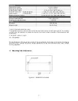
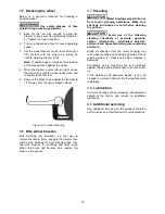
5.4

  Securing the grinder 

To prevent the machine from moving during 
operation, it should be securely mounted to a work 
surface or grinder stand. Fasteners for mounting 
are not included with the grinder. 

1.  Align the mounting holes on the grinder with 

predrilled holes in a bench or grinder stand. 
Figure 4-1 shows hole centers for mounting. 

2.  Insert M8 (or 5/16”) bolts through the holes 

and tighten, using washers and nuts. 

An optional pedestal stand (not included) is 
available from JET for your grinder. See 

sect. 11.0. 

IMPORTANT:

 The grinder’s base plate contains 

ventilation holes for keeping the circuit board at an 
acceptable temperature. These holes should not 
be obstructed. If the rubber pads are removed for 
mounting to a table, allow an opening in the table 
below the grinder for air circulation. However, it is 
recommended the rubber pads be left on, as they 
allow air circulation as well as vibration dampening. 

Summary of Contents for IBGM-8VS

Page 1: ...8 inch Industrial Bench Grinder with Multitool Attachment Model IBGM 8VS JET 427 New Sanford Road LaVergne Tennessee 37086 Part No M 577218 Ph 800 274 6848 Edition 1 05 2018 www jettools com Copyright 2018 JET This pdf document is bookmarked ...

Page 2: ...to the State of California to cause birth defects and in some cases cancer California Health and Safety Code Section 25249 5 et seq 13 Do not operate this machine while tired or under the influence of drugs alcohol or any medication 14 Make certain the switch is in the OFF position before connecting the machine to the power supply 15 Make certain the machine is properly grounded 16 Make all machin...

Page 3: ... changing accessories 36 Direction of feed Feed work into a blade or cutter against the direction of rotation of the blade or cutter only 37 Do not overtighten wheel nut 38 Frequently clean grinding dust from beneath grinder 39 Use grinding wheel suitable for speed of grinder 40 Inspect abrasive wheels for cracks or other forms of damage Perform a ring test to check wheel integrity Do not use a fa...

Page 4: ...ting controls 11 7 2 Precautions 12 8 0 Adjustments 12 8 1 Eye shield tilt adjustment 12 8 2 Spark guard 12 8 3 Tool rest 12 8 4 Belt tracking 13 8 5 Platen adjustment 13 9 0 User maintenance 13 9 1 Ring test 13 9 2 Care of grinding wheels 13 9 3 Changing wheels 13 9 4 Wheel balancing 14 9 5 Dressing the wheel 15 9 6 Wire wheel brushes 15 9 7 Cleaning 15 9 8 Lubrication 15 9 9 Additional servicing...

Page 5: ...n this document The operator is encouraged to familiarize him herself with ANSI B7 1 Safety Requirements for Use Care and Protection of Abrasive Wheels If there are questions or comments please contact your local supplier or JET JET can also be reached at our web site www jettools com Retain this manual for future reference If the grinder transfers ownership the manual should accompany it Read and...

Page 6: ...ial aluminum oxide Wheel grit 36 grit Wheel flange diameter 3 3 8 in 85mm Wheel speed Variable 900 3600 RPM Arbor nut maximum tightening torque 20 lbf ft 270 kgf cm Tool rest distance to wheel adjustable Abrasive belt Belt size 36 x 2 in 915 x 51 mm Belt grit material 100 grit zirconia alumina Belt speed 5000 SFPM Contact wheel p n 577115 3 1 2 Dia x 2 in 51 x 89 mm Platen size 2 x 6 in 50 8 x 153...

Page 7: ...weight 80 lb 36 3 kg Shipping weight 86 5 lb 40 kg 1 subject to local national electrical codes 2 The specified values are emission levels and are not necessarily to be seen as safe operating levels As workplace conditions vary this information is intended to allow the user to make a better estimation of the hazards and risks involved only L length W width H height n a not applicable The specifica...

Page 8: ...power switch is in the OFF position Do not plug in the grinder to power until it is inspected for shipping damage fully assembled and moved to its permanent location Failure to comply may cause serious injury Do not operate this grinder without all guards and shields in place and in working order Failure to comply may cause serious injury Chipped or cracked wheels can break up and cause serious da...

Page 9: ...ntains threaded mounting holes 2 Tighten screws H 5 8 Tool rest Refer to Figure 5 3 1 Install tool rest M by inserting two 3 8 x 3 4 hex cap screws J through two 3 8 flat washers L through the tool rest M into the wheel housing 2 The tool rest should be adjusted to within 1 16 of the grinding wheel or other accessories being used As the wheel wears down the tool rest must be readjusted to maintain...

Page 10: ... for electric current to reduce the risk of electric shock This tool is equipped with an electric cord having an equipment grounding conductor and a grounding plug The plug must be plugged into a matching outlet that is properly installed and grounded in accordance with all local codes and ordinances Do not modify the plug provided if it will not fit the outlet have the proper outlet installed by ...

Page 11: ...6 16 14 12 12 16 14 12 Not Recommended Extension Cord Recommendations Table 2 6 3 Voltage conversion To change voltage input to 230 volt on the IBGM 8VS Grinder remove existing plug from grinder cable and attach a UL CSA listed plug designed for 230V power 7 0 Operation Always use approved safety glasses or face shield while operating tool Failure to comply may cause serious injury A bench grinder...

Page 12: ...eep a water pot filled with water and dip your work into it regularly to prevent overheating Overheating can weaken metals Do not apply water directly to grinding wheel 8 Do not use the side of the grinding wheel this puts dangerous stress on the wheel 9 When wheel becomes loaded or dull use an approved grinding wheel dresser and dress the wheel face 7 2 2 Belt and Disc grinding 1 Remove belt befo...

Page 13: ... perform this simple test on the replacement wheel 1 Loop a piece of string through the grinding wheel hole and suspend the wheel by holding up the string 2 Tap the wheel with a piece of scrap wood or a wooden dowel 3 A good wheel will ring a defective wheel will thud Discard any wheel that does not ring An internal defect may not be apparent by visual inspection alone The ring test may identify a...

Page 14: ...ncentricity If the outside face is not rotating concentric to arbor try shifting the wheel closer to arbor centerline before tightening the nut Another method of achieving concentricity is the use of a wheel dresser Dressing is the removal of the current layer of abrasive to expose a fresh surface A wheel dresser is also used to true a wheel that is to make the grinding surface parallel to the too...

Page 15: ...Use coarse wire brushes for hard cleaning jobs Use fine wire brushes for polishing and finish work When the brush tips become dull reverse the brush on the grinder 9 7 Cleaning Metal shavings may still be hot from recent grinding operations Make sure shavings and debris are cold before cleaning the grinder Avoid use of the following cleaning chemicals or solvents gasoline carbon tetrachloride chlo...

Page 16: ...try again Incorrect fuse Use time delay fuse or go to circuit with higher rated fuse or breaker Wheels cannot rotate because of obstruction Unplug and turn grinding wheel by hand to ensure free movement Clear any obstructions and restart Undersized extension cord Use correct size extension cord Short circuit in line cord or plug Inspect cord or plug for damaged insulation and shorted wires Short c...

Page 17: ...place it Adjust wobble by rotating flange as needed Improper mounting Secure machine firmly to bench or stand 10 2 Digital readout error codes Table 5 Message Possible Cause Correction OCL Internal electronic overload has been tripped Do not overload motor reduce pressure of workpiece against wheels OH IGBT protection activated Inspect wire connections to U V W for possible short circuits Verify t...

Page 18: ...Reducer 3 in to 2 5 in 414811 0 6M Hose Heat Resistant ø2 5 x 24 4 in 12 0 Replacement Parts Replacement parts are listed on the following pages To order parts or reach our service department call 1 800 274 6848 Monday through Friday 8 00 a m to 5 00 p m CST Having the Model Number and Serial Number of your machine available when you call will allow us to serve you quickly and accurately Non propr...

Page 19: ...19 12 1 1 IBGM 8VS Variable Speed Grinder w Multitool Attachment Exploded View ...

Page 20: ...t Left 1 28 TS 0680041 Flat Washer 3 8 2 29 IBG8 29 Hex Cap Screw 3 8 16 x 3 4 2 31 TS 0060011 Hex Cap Screw 3 8 16 x 1 2 4 32 IBG8 32 Spark Guard Left 1 33 IBG8 33 Eye Shield 1 34 IBG8 34 Eye Shield Bracket Left 1 35 IBG8 35 Eye Shield Plate 1 36 IBG8 36 Truss Head Screw 3 16 24 x 1 2 2 37 IBG8 37 Knob 1 38 TS 0680021 Flat Washer 1 4 1 41 TS 2284082 Pan Head Screw M4 x 8 4 42 IBG8 42 Screw M5 x 0...

Page 21: ...21 13 0 Electrical Connections IBGM 8VS Grinder ...

Page 22: ...itional action needed JET has Authorized Service Centers located throughout the United States For the name of an Authorized Service Center in your area call 1 800 274 6846 or use the Service Center Locator on the JET website More Information JET is constantly adding new products For complete up to date product information check with your local distributor or visit the JET website How State Law App...

Page 23: ...23 This page intentionally left blank ...

Page 24: ...24 427 New Sanford Road LaVergne Tennessee 37086 Phone 800 274 6848 www jettools com ...

Reviews: