background image


12

8.0

  Adjustments 

8.1

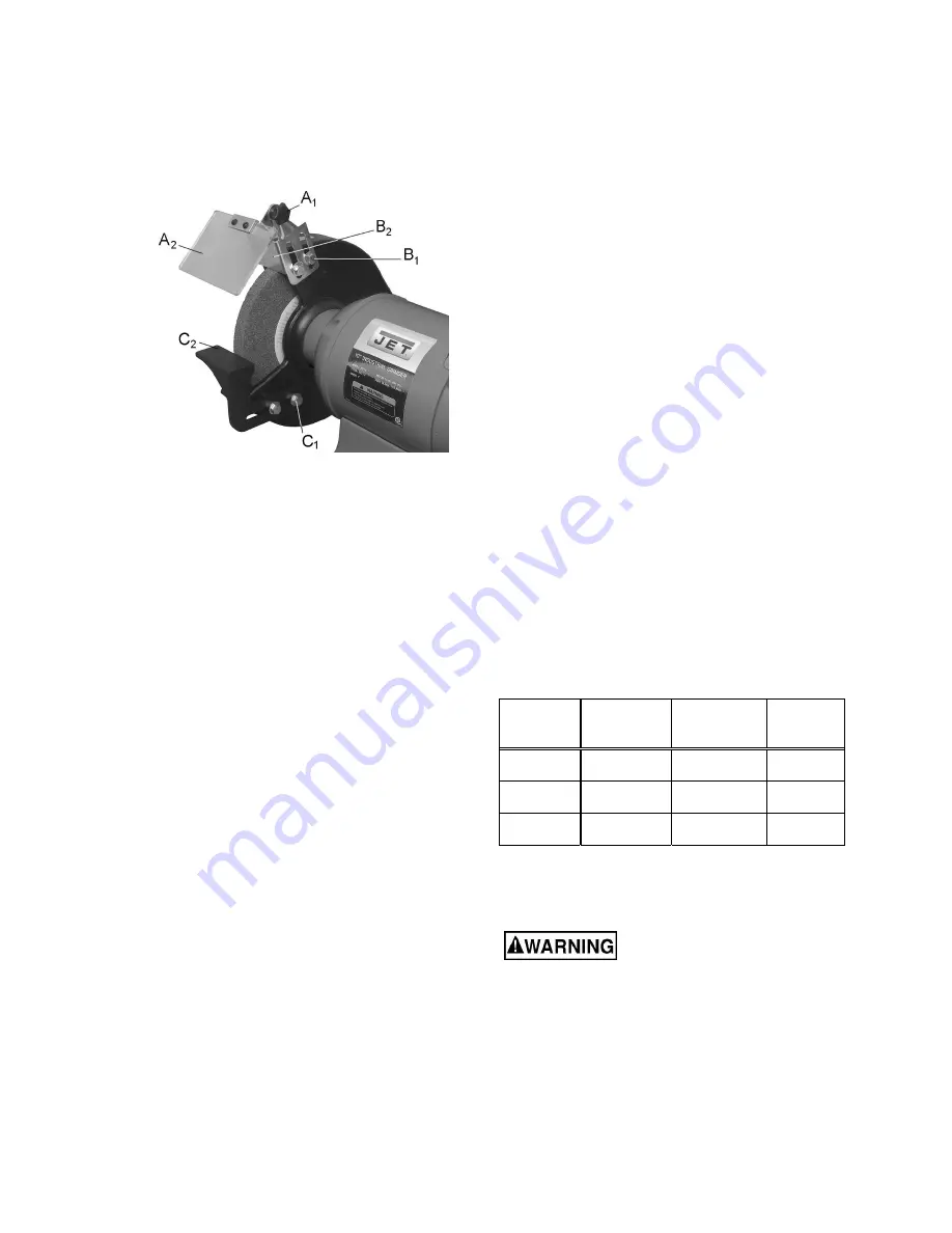
  Eye Shield Tilt Adjustment 

1.  Loosen lock knob (A

1

, Figure 10). 

2.  Adjust eye shield (A

2

) to the desired tilt angle. 


Figure 10:  eye shield adjustment 

8.2

  Spark Guard 

As the wheel wears down, the spark guards must 
be re-adjusted to maintain a 1/16" distance. 

Refer to Figure 10. 

1.  Loosen two hex cap screws (B

1

) with a 14mm 

wrench. 

2.  Slide the spark guard (B

2

) to 1/16" distance 

from the grinding wheel surface. 

3.  Tighten screws (B

1

). 

8.3

  Tool Rest 

As the wheel wears down, the tool rests must be 
re-adjusted to maintain a 1/16" distance. 

Refer to Figure 10. 

1.  Loosen two hex cap screws (C

1

) with a 14mm 

wrench. 

2.  Slide the tool rest (C

2

) to a distance of 1/16" 

from the grinding wheel. 

3.  Tighten screws (C

1

). 

9.0

  Maintenance 

For safety, turn the switch to OFF and remove plug 
from the power source outlet before adjusting and 
maintaining the bench grinder. If the power cord is 
worn, cut or damaged in any way, have it replaced 
immediately. 

9.1

  Ring Test 

Before replacing a grinding wheel, perform this 
simple test on the replacement wheel: 

1.  Loop a piece of string through the grinding 

wheel hole and suspend the wheel by holding 
up the string. 

2.  Tap the wheel with a piece of scrap wood or a 

wooden dowel. 

3.  A good wheel will "ring"; a defective wheel will 

"thud". Discard any wheel that does not "ring".  

An internal defect may not be apparent by visual 
inspection alone. The ring test may identify an 
internal crack or void. 

9.2

  Care of Grinding Wheels 

In normal use, grinding wheels may become 
cracked, grooved, rounded at the edges, chipped, 
out of true or loaded with foreign material. 

Cracked wheels should be replaced 
IMMEDIATELY. The other conditions can be 
remedied with a dressing tool. New wheels 
sometimes require dressing to make them round. 
See 

sect. 10.5.


9.3

  Changing Wheels 

The JET Series bench grinders come equipped 
with general purpose grinding wheels. Wheels vary 
according to types of abrasive, hardness, grit size, 
and structure. Contact your local distributor for the 
proper grinding wheel or wire wheel brush for your 
application. 

If you replace a wheel, obtain one with a safe rated 
speed at least as high as the 

NO


LOAD RPM 

marked on the grinder's nameplate. Refer to Table 
2 to determine correct dimensions for the 
replacement wheel. 

Model 

Wheel 

Diameter 

Maximum 

Width 

Center 

Hole 

IBG-8 

8" 1" 

5/8" 

IBG-10 

10" 1" 1" 

IBG-12 

12” 2” 

1-1/4” 

Table 2 

Your bench grinder will accept most polishing and 
buffing wheels available at dealers and hardware 
stores. 


The use of any other 

accessory is not recommended and may result 
in serious injury! 

To change a wheel 

(see Figure 11)

1.  Disconnect grinder from power source. 

2.  Loosen spark guard (B) and tool rest (C) and 

move them away from the wheel. 

3.  Remove wheel guard using a cross-point or 

flathead screwdriver. 

Summary of Contents for IBG-8

Page 1: ...ions and Parts Manual IBG Series Industrial Grinders Models IBG 8 IBG 10 IBG 12 JET 427 New Sanford Road LaVergne Tennessee 37086 Part No M 578008 Ph 800 274 6848 Revision E 09 2018 www jettools com C...

Page 2: ...15 Keep safety guards in place at all times when the machine is in use If removed for maintenance purposes use extreme caution and replace the guards immediately after completion of maintenance 16 Ch...

Page 3: ...the grinding operation 42 Do not crowd the work so that the wheels slow 43 Tool rests should be adjusted to approximately 1 16 from wheel surface 44 Do not grind on the side of a wheel do all work on...

Page 4: ...9 0 Maintenance 12 9 1 Ring Test 12 9 2 Care of Grinding Wheels 12 9 3 Changing Wheels 12 9 4 Wheel balancing 13 9 5 Dressing the wheels 14 9 6 Wire wheel brushes 14 9 7 Cleaning 14 9 8 Lubrication 14...

Page 5: ...operator is encouraged to familiarize himself herself with ANSI B7 1 Safety Requirements for Use Care and Protection of Abrasive Wheels If there are questions or comments please contact your local su...

Page 6: ...g torque 20 lbf ft 270kgf cm 20 lbf ft 270kgf cm 20 lbf ft 270kgf cm Toolrest distance to wheel adjustable adjustable adjustable Materials Arbor steel steel steel Base cast iron cast iron cast iron Bo...

Page 7: ...ipping 70 lb 31 73 kg 124 lb 56 60 kg 208 lb 94 50 kg The specifications in this manual were current at time of publication but because of our policy of continuous improvement JET reserves the right t...

Page 8: ...o a workbench or stand For your safety do not plug the grinder into a power source until all assembly and adjustments are complete Be sure that the bench grinder is unplugged and the power switch is i...

Page 9: ...this 1 16 distance 5 7 Eye shields Refer to Figure 6 The eye shields O are identical and will fit on either side of the grinder 1 Insert two 3 16 x 1 2 truss head screws H through the bracket eye shie...

Page 10: ...ury Use only 3 wire extension cords that have 3 prong grounding plugs and 3 pole receptacles that accept the tool s plug Repair or replace damaged or worn cord immediately 2 Grounded cord connected to...

Page 11: ...stop The safety key A1 can be removed to prevent unauthorized use of the grinder The safety key must be inserted to restart the grinder IBG 12 Push green button to start grinder Push red button to sto...

Page 12: ...l that does not ring An internal defect may not be apparent by visual inspection alone The ring test may identify an internal crack or void 9 2 Care of Grinding Wheels In normal use grinding wheels ma...

Page 13: ...ace is not rotating concentric to arbor try shifting the wheel closer to arbor centerline before tightening the nut Another method of achieving concentricity is the use of a wheel dresser Dressing is...

Page 14: ...ool rest 5 Remove the dresser and adjust the tool rest to 1 16 away from the newly dressed wheel Figure 13 wheel dressing 9 6 Wire wheel brushes Wire brushing provides a fast way to remove rust scale...

Page 15: ...y time delay fuse or go to circuit with higher rated fuse of circuit breaker Wheels cannot rotate because of obstruction Unplug and turn grinding wheel by hand to ensure free movement Clear any obstru...

Page 16: ...ess so hard Electrical circuit overload too many electrical machines running on same circuit Turn off other machines and try again Incorrect fuse or circuit breaker Have electrician upgrade service to...

Page 17: ...ollection Stand 414825 Reducer 3 in to 2 5 in 414811 0 6M Hose Heat Resistant 2 5 x 24 4 in 12 0 Replacement Parts Replacement parts are listed on the following pages To order parts or reach our servi...

Page 18: ...18 12 1 1 IBG 8 Grinder Exploded View...

Page 19: ...ool Rest Left 1 28 TS 0680041 Flat Washer 3 8 4 29 IBG8 29 Hex Cap Screw 3 8 16 x 5 8 4 30 IBG8 30 Tool Rest Right 1 31 TS 0060011 Hex Cap Screw 3 8 16 x 1 2 2 32 IBG8 32 Spark Guard Left 1 33 IBG8 33...

Page 20: ...55 TS 0680041 Flat Washer 3 8 2 56 TS 0060011 Hex Cap Screw 3 8 16 x 1 2 2 57 IBG8 33 Eye Shield 1 58 IBG8 35 Eye Shield Plate 1 59 IBG8 36 Truss Head Screw 3 16 24 x 1 2 2 60 IBG8 37 Knob 1 61 TS 06...

Page 21: ...21 12 2 1 IBG 10 Grinder Exploded View...

Page 22: ...Hex Nut Left Hand Thread 5 8 11UNC 1 27 IBG10 27 Wheel Cover 2 28 IBG8 26 Truss Head Screw 1 4 20 x 3 4 10 29 IBG10 29 Tool Rest Left 1 30 TS 0680041 Flat Washer 3 8 4 31 TS 0060031 Hex Cap Screw 3 8...

Page 23: ...her 3 8 2 56 TS 0060011 Hex Cap Screw 3 8 16 x 1 2 2 57 IBG8 33 Eye Shield 1 58 IBG8 35 Eye Shield Plate 1 59 IBG8 36 Truss Head Screw 3 16 24 x 1 2 2 60 IBG8 37 Knob 1 61 TS 0680021 Flat Washer 1 4 1...

Page 24: ...24 12 3 1 IBG 12 Grinder Exploded View...

Page 25: ...ft 1 27 TS 0680041 Flat Washer 3 8 4 28 TS 0060031 Hex Cap Screw 3 8 16 x 3 4 4 29 IBG12 29 Tool Rest Right 1 30 TS 0060011 Hex Cap Screw 3 8 16 x 1 2 2 31 IBG12 31 Spark Guard Left 1 32 IBG12 32 Eye...

Page 26: ...680041 Flat Washer 3 8 2 56 TS 0060011 Hex Cap Screw 3 8 16 x 1 2 2 57 IBG12 32 Eye Shield 1 58 IBG12 34 Eye Shield Plate 1 59 IBG8 36 Truss Head Screw 3 16 24 x 1 2 1 60 IBG8 37 Knob 1 61 TS 0680021...

Page 27: ...u 13 1 1 IBGS 01 Base 1 2 IBGS 02 Post includes 3 and 4 1 3 IBGS 03 Insert Ring 2 4 IBGS 04 Pin 4 x 14 2 5 IBGS 05 Water Pot Holder 1 6 IBGS 06 Water Pot 1 7 IBGS 07 Platform 1 8 TS 1540071 Hex Nut M1...

Page 28: ...Stamped Stand Front 1 3 DBGS 03 Base 1 4 DBGS 04 Stamped Stand Cover 1 5 DBGS 05 Water Pot Holder 1 6 IBGS 06 Water Pot 1 7 TS 0070011 Hex Cap Screw 1 2 13 x 1 8 8 TS 0720111 Lock Washer 1 2 8 9 TS 08...

Page 29: ...29 13 0 Electrical Connections 13 1 Wiring Diagram for IBG 8...

Page 30: ...30 13 2 Wiring Diagram for IBG 10...

Page 31: ...31 13 3 Wiring Diagram for IBG 12...

Page 32: ...tional action needed JET has Authorized Service Centers located throughout the United States For the name of an Authorized Service Center in your area call 1 800 274 6846 or use the Service Center Loc...

Page 33: ...33 This page intentionally left blank...

Page 34: ...34 This page intentionally left blank...

Page 35: ...35 This page intentionally left blank...

Page 36: ...36 427 New Sanford Road LaVergne Tennessee 37086 Phone 800 274 6848 www jettools com...

Reviews: