


9
EVBS-20
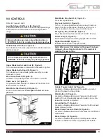
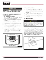
9.0 CONTROLS
Refer to Figures 2 and 3.
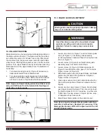
Low/High Range Shift Lever (B, Figure 2) -
Pull toward front of machine to shift into low speed range.
Push toward rear of machine to shift into high speed
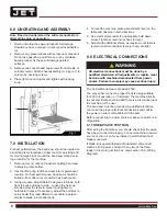
range.
Variable Speed Knob (C, Figure 2) -
Turn clockwise to increase speed and counterclockwise to
decrease speed.
Upper Blade Guide Lock Knob (D, Figure 2) -
Turn counterclockwise to loosen and clockwise to tighten.
Upper Blade Guide Knob (E, Figure 2) -
Turn clockwise to raise blade guide assembly; counter-
clockwise to lower.
Work Lamp Switch (F, Figure 2) -
Located on top of lamp shade; turns lamp on and off.
Shear Lever (G, Figure 2) -
UP position allows insertion of blade end into shear. Pull
lever DOWN to cut blade.
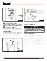
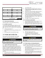
Main Motor Start Switch (H, Figure 3) -
Press to start band saw.
Press again to start air com-
pressor.
Main Motor Stop Switch (I, Figure 3) -
Press to stop band saw.
Key Lock Switch (J, Figure 3) -
Turn to 12 o’clock position and remove key to lock out
power from the control panel. Insert key and turn to 3
o’clock position to turn on power to control panel.
Emergency Stop Switch (K, Figure 3) -
Press to stop all machine functions. Turn 90° to reset.
Power Lamp (L, Figure 3) -
Illuminated when power is being supplied to band saw.
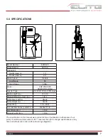
Digital Readout (M, Figure 3) -
Indicates blade speed in feet per minute.
Note: After saw is fi rst started or the speed has been
changed, allow at least a minute for the readout to
stabilize the new setting.
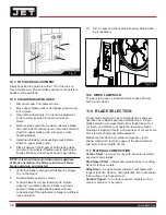
Grinder Toggle Switch (N, Figure 4) -
Located on blade welder panel. Flip switch up to start
grinder; fl ip down to stop grinder.
Weld Button (O, Figure 4) -
Located on blade welder panel. Press and hold to start
welding. Shuts off automatically when weld is done. Re-
lease when weld is completed.
Anneal Button (P, Figure 4) -
Located on blade welder panel. Press and hold to anneal
blade, release to stop.
Blade Clamp Pressure Knob (Q, Figure 4) -
Located on blade welder panel. Sets pressure for different
width blades.
Blade Clamps (R, Figure 4) -
Located on blade welder panel. DOWN position allows
insertion of blade into clamp. Up position locks blade.
Fig. 3
H
I
K
J
L
M
Fig. 2
C
B
E
D
G
F
!
Move low/high range lever only while machine is
STOPPED. Failure to comply may damage gearbox.
!
Turn variable speed knob only while machine is
RUNNING. Failure to comply may damage gearbox.
Summary of Contents for 891100
Page 34: ...34 Vertical Band Saw 19 0 WIRING DIAGRAM ...
Page 35: ...35 EVBS 20 NOTES ...
Page 36: ...36 Vertical Band Saw NOTES ...