11
Note:
When raising the roller higher above the
table, the available range is from .003” to .006”
See Fig. 13.
The table rollers are factory set for average
planing and are parallel to the table surface. If you
desire to adjust the table rollers higher or lower,
proceed as follows:
1. Disconnect machine from power source.
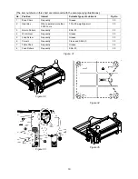
2. Lay a straight edge (B, Fig. 14) across both
rollers.
3. On one side of the table, loosen the screws
(C, Fig. 14) with a hex wrench, and turn the
eccentric shafts (D, Fig. 14) to raise or lower
the rollers.
4. When the proper height is achieved, tighten
screws (C, Fig. 14).
5. Adjust the rollers from the opposite side of the
table in the same manner.
Important:
Be sure that the height of front and
rear rollers are the same. The table rollers must
always be set parallel to the table.
Adjusting Table Extension Rollers
1. Place a straight edge over the extension roller
and the table, as shown in Fig. 15, to make
sure the extension roller and table are at the
same height. If necessary, adjust the table
extension rollers as follows:
2. Loosen the screws and washers (A, Fig. 15)
to move the extension roller to the proper
position, then retighten the screws.
3. Adjust both front and rear extension rollers in
the same manner.
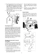
Figure 13
Figure 14
Figure 15
Summary of Contents for 708528
Page 25: ...25 Head Assembly Exploded View ...
Page 29: ...29 Base and Column Assembly ...
Page 31: ...31 Gearbox Assembly ...
Page 33: ...33 230V 5HP Single Phase A2 14NO 17 13NO O ManAuto 97 95 96 98 R R 4T2 6T3 2T1 3L2 5L3 1L1 A1 ...
Page 34: ...34 230V 5HP Three Phase 4T2 ManAuto 97 A2 95 R 96 O R 14NO 6T3 17 98 2T1 3L2 13NO 5L3 1L1 A1 ...
Page 35: ...35 460V 5HP Three Phase 4T2 ManAuto 97 A2 95 R 96 O R 14NO 6T3 17 98 2T1 3L2 13NO 5L3 1L1 A1 ...
Page 36: ...36 427 New Sanford Road LaVergne Tennessee 37086 Phone 800 274 6848 www jettools com ...


