INSTALLATION INSTRUCTIONS
Step # 7
CONNECTING THE ELECTRICAL CONNECTIONS
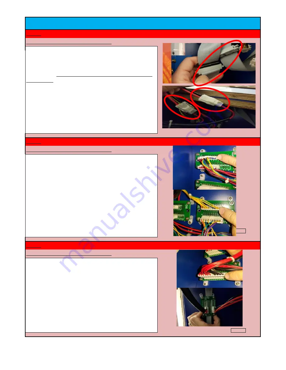
Connect the 12 Pin connector to the lower left board - this is a 12 Pin
connector with only 10 wires. Then connect the 6 Pin connector to the
board located to the right of the chain assembly - (3 red wires / 3
black wires).
Step # 8
Step # 9
CONNECTING THE ELECTRICAL CONNECTIONS
Check Box When This Step is Complete
The remaining six connectors will all be board connections. The 8 Pin
connector should be plugged into the upper left board. The 10 Pin
connector should be plugged into the upper right board. (Note that
this is a 10 pin connector but only 8 positions are used).
Please also
note that these connections must be pushed in all the way and
indexed with connections aligned left to right.
After securing Section#3 to the main cabinet, open up the rear access
doors and clear away any packaging material from around the scoring
chain assembly.
CUT THE ZIP TIES SECURING THE CHAIN ASSEMBLY
TO THE TRACK
. Locate the wire connections stored in the section # 3
header - pull the two ribbon cables and six wire connections down
through the upper access hole. First connect the two gray ribbon cable
connections. Then, make the two connections in the lower right
pictures. These should be a 2 pin connection (red and black wires) and
a 3 pin connection (black, red and yellow). Make sure when making
these wire to wire Molex connections that you do not push a pin out
of the connector.
CONNECTING THE ELECTRICAL CONNECTIONS
Check Box When This Step is Complete
JET Games
Kahuna's Big Wave Service Manual
14


