background image

2

I M P O R T A N T   S A F E T Y   I N S T R U C T I O N S

SAVE THESE INSTRUCTIONS

WARNING:

When using your appliance, always follow

basic precautions, including the following:

• Use the refrigerator only for its

intended purpose.

• To prevent possibility of hazard due to

electrical shock, never plug the refriger-
ator into a receptacle which has not
been grounded adequately and in accor-
dance with the local and national elec-
trical codes. See the

warning and

grounding instructions.

• This refrigerator must be properly

installed in accordance with its installa-
tion instructions.

• Turn the power to your refrigerator off

before cleaning or replacing light bulbs.

• In case of power failure, minimize door

openings. If the power failure is of a long
duration, protect the food by placing
blocks of dry ice on top of the packages
or check with a local frozen foods
locker about temporary storage. Frozen
foods which have thawed completely
should not be refrozen and should be
discarded.

NOTE:

The power pad in the fresh food com-
partment stops cooling and turns off
the lights. It does not shut power to the
unit off. Prior to changing light bulbs or
other servicing, the Main Power switch
in the upper machine compartment
must be switched to 

OFF 

or

“O”

.

• Any  electrical service cord that

becomes frayed or damaged should be
immediately repaired or replaced.
Never unplug your appliance by pulling
on the power cord.

• Your refrigerator should not be oper-

ated in the presence of explosive fumes.

• Children should not climb, hang or

stand on the shelves of this refrigerator.

• To prevent the unit from tipping for-

ward and to provide a stable installa-
tion, the unit must be secured in place
with the anti-tip device (See separate
installation instructions provided with
this refrigerator).

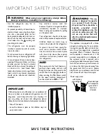
WARNING: 

This ap-

pliance is designed to operate
on a normal 115 volt, 15 amp,
60 cycle line.There should be a
separate,

grounded circuit

serving this appliance only. Do
not use an extension cord. Do
not use any device that will
alter the electrical performance
of this appliance.

This appliance is equipped with a three-
pronged grounding plug for your protec-
tion against possible electrical shock haz-
ards. It must be plugged into a grounded
receptacle. Where a standard two-prong
wall receptacle is encountered, it is the
personal responsibility and obligation of
the customer to have it replaced with a
properly grounded three-prong wall recep-
tacle. Do not, under any circumstances, cut
or remove the third (ground) prong from
the power cord. Do not use an adapter
plug. Do not use an extension cord. Do not
use a Ground Fault Circuit Interrupter.

Power supply cord

with 3-prong

grounding plug

Grounded type

wall receptacle

(ground fault

circuit not

allowed)

IMPORTANT:

Child entrapment and suffocation are not problems of
the past. Junked or abandoned refrigerators are still
dangerous…even if they will sit for “just a few days.” If
you are getting rid of your old refrigerator, please
follow the instructions below to help prevent accidents.

• Take off the doors.

• Leave the shelves in place so that children may not

easily climb inside.

Summary of Contents for Luxury Series

Page 1: ...ty damage or personal injury for improper service procedures done by an unqualified person 16021730 July 2002 Service Service Manual for Jenn Air models ThisBaseManualcoversIntegrated Side by Side Refrigerators Refer to individual Technical Sheet for information on specific models Integrated Side by Side Refrigerators ...

Page 2: ...es If performing service on your own product assume responsibility for any personal injury or property damage which may result To locate an authorized servicer please consult your telephone book or the dealer from whom you purchased this product For further assistance please contact MAYTAG APPLIANCES SALES COMPANY OR U S and Canada 1 800 Jenn Air ATTN Jenn Air CAIR Center CALL U S customers using ...

Page 3: ...sor 12 Brazing 12 Refrigerant Flow 13 CabinetAir Flow 14 Ice and Water Flow Diagram 15 Water Valves Diagram 16 Troubleshooting Chart 17 System Diagnosis 20 Disassembly Procedures Compressor Replacement 23 Condenser Replacement 24 Evaporator Replacement 25 Heat Exchanger Replacement 27 Condenser Fan 28 Freezer Fan 28 Fresh Food Fan 28 Defrost Heater 29 Drain Pan and Drain Tube Heater 30 Defrost The...

Page 4: ...lace compressor Ground test 1 Disconnect power to refrigerator 2 Remove compressor leads and use an ohmmeter set on highest scale 3 Touch one lead to compressor body clean point of contact and other probe to each compressor terminal If reading is obtained compressor is grounded and must be replaced Operation test If voltage and motor winding tests do not show cause for failure perform the followin...

Page 5: ...ator and into compressor through suction line Leaks in condenser can usually be detected by using an electronic leak detector or soap solution Look for signs of compressor oil when checking for leaks A certain amount of compressor oil is circulated with refrigerant Leaks in post condenser loop are rare because loop is a one piece copper tube For minute leaks 1 Separate condenser from rest of refri...

Page 6: ...ischarged from capillary to expand into refrigerant gas Expansion cools evaporator tube and fin temperature to approximately 20 F transferring heat from freezer section to refrigerant Passing through suction line to compressor the refrigerant picks up superheat a relationship between pressure and temperature that assures complete vaporization of liquid refrigerant as the result of capillary tube s...

Page 7: ...rvicing of HFC134a systems Verify equipment is confirmed by manufacturer as being compatible with HFC134a and ester oil system Equipment must be exclusively used for HFC134a Exclusive use of equipment only applies to italic items Evacuation pump Check with vacuum pump supplier to verify equipment is compatible for HFC134a Robinair Model 15600 2 stage 6 cubic feet per minute pump is recommended Fou...

Page 8: ...Ensure all ground wires are connected before certifying unit as repaired and or operational WARNING Testing Systems Containing No Refrigerant Charge 1 Connect cylinder of nitrogen through gauge manifold to process tube of compressor and liquid line strainer 2 Open valves on nitrogen cylinder and gauge manifold Allow pressure to build within sealed system 3 Check for leaks using soap suds If a leak...

Page 9: ...ary precautions against high temperaturesrequiredforbrazing 7 Remove and replace restricted device 8 Evacuate sealed system 9 Charge system to specification NOTE Do not use captured or recycled refrigerant in Maytag units Captured or recycled refrigerant voids any Maytag and or compressor manufacturer s warranty NOTE Charge system with exact amount of refrigerant Refer to unit nameplate for correc...

Page 10: ...ure refrigerant repair leak and begin at step 1 Charging NOTE Do not use captured or recycled refrigerant in Maytag units Captured or recycled refrigerant voids any warranty NOTE Charge system with exact amount of refrigerant Refer to unit serial plate for correct refrigerant charge Inaccurately charged system will cause future problems To charge system 1 Close valves A to vacuum pump and C to vac...

Page 11: ...me Properties Characteristics CFC12 HFC134a Ozone Depletion Potential ODP 1 0 0 0 Global Warming Potential GPW 3 2 0 27 Molecular weight 121 102 Boiling point at 1 atmosphere 22 F 30 C 15 F 126 C Vapor pressure at 77 F 25 C 80 psig 82 psig Liquid density at 77 F 25 C 82 lb ft 3 75 lb ft 3 Flammability No No High side system operating Pressure at 65 F 18 C HFC134a approximately 3 psig higher than C...

Page 12: ...ts test points and temperature relationship test for unit being tested Temperature testing is accomplished by using 3 lead thermocouple temperature tester in specific locations Test point T 1 is outlet on evaporator coil and T 2 is inlet Test point T 3 is suction tube temperature midway between where armaflex ends and suction port of compressor approximately 12 inches from compressor Thermocouple ...

Page 13: ...13 16021730 Rev 0 Refrigerant Flow Side by Side Refrigerant Flow Diagram ...

Page 14: ...16021730 Rev 0 14 Cabinet Air Flow Side by Side Cabinet Air Flow Diagram ...

Page 15: ...6021730 Rev 0 Side by Side Ice and Water Flow Diagram Ice and Water Dispenser Diagram Ice Maker 5 16 Water line to Dispenser 1 4 Water Line Water Coil Secondary Water Valve Water Filter Primary Water Valve ...

Page 16: ...16021730 Rev 0 16 Water Valves Diagram Bottom View Back View Primary Valve Secondary Valve Filter Head Bypass ...

Page 17: ...r setting Poor door seal Level cabinet Adjust hinges Replace gasket Refrigerator airflow Check auto damper is opening by removing grille With door open damper should open Replace if faulty Interior light remains on Check switch Replace if necessary Faulty condenser fan or evaporator fan Check fan and wiring Replace if necessary Refrigerator section too warm Faulty compressor Replace compressor Tro...

Page 18: ...t shortage or restriction Check for leak or restriction Repair evacuate and recharge system Refrigerant overcharge Check for overcharge Evacuate and recharge system Unit runs continuously Air in system Check for low side leak Repair evacuate and recharge system Loose flooring or floor not firm Repair floor or brace floor Cabinet not level Level cabinet Tubing in contact with cabinet other tubing o...

Page 19: ...charge system Supply voltage out of specification Check input voltage Correct any supply problems Faulty fan motor Check fan motor Replace if failed Restricted air flow Check condenser and grille for dirt Clean Frost or ice on evaporator Refrigerant shortage or restriction Check for leak or restriction Repair evacuate and recharge system Troubleshooting Chart To avoid risk of electrical shock pers...

Page 20: ...tem the refrigerant will flood out and cause the suction line to frost or sweat The cause of this problem should be corrected rather than to purge refrigerant from the sytem Running the freezer section colder than necessary 2 to 1 F is considered normal package temperatures or continuous running of the compressor for a variety of reasons or the freezer fan motor not running may give the indication...

Page 21: ...tem replace the drier filter evacuate and recharge with the specified refrigerant charge If the unit performs normally three possibilities exist 1 refrigerant loss 2 partially restricted drier filter and 3 moisture in system If the unit performs as it previously did you may have a restricted capillary line or condenser or kinked line Find the point of restriction and correct it A restriction reduc...

Page 22: ...temperature raises Refrigerators installed in ambient temperatures lower than 60 F will not perform as well because the pressures within the system are generally reduced and unbalanced This means that the lower head pressure forces less liquid refrigerant through the capillary line The result is the symptoms of a refrigerant shortage The lower the ambient temperature the more pronounced this condi...

Page 23: ...ect the refrigerant tubing to the compressor stubs using silfos on copper to copper joints and silver solder and flux on steel to copper joints 11 Locate and remove old drier Install new drier The new driver is installed in the following manner a Carefully bend the old drier and tubing away from electrical parts b Use steel wool or fine emery paper to clean the capillary tube 3 inches from the ori...

Page 24: ...ormation explains how to successfully replace the condenser for any model covered in this manual 1 Remove the Machine compartment access door 2 Turn the main power switch in the machine com partment to the off position See figure 1 Main Power Switch Centigrade Fahrenheit Switch Figure 1 3 Remove the high side slide rail mounting screw See figure 2 Figure 2 4 Slide the highside assembly forward int...

Page 25: ...tubing Clean and connect the Yoder loop to the outer tubing of the condenser 14 Solder all joints Silver solder and proper flux should be used on copper to steel or steel to steel joints Excess flux should be wiped off all tubing 15 Remove and replace the old drier Do not allow more than 1 2 of the cap tube to penetrate the drier 16 Install the new drier using silver solder with the proper flux 17...

Page 26: ...g Screw Mounting Screw Figure 2 11 Remove the auto damper stepper motor bracket mounting screws See figure 2 Figure 3 12 Remove the evaporator cover mounting screws See figure 3 13 Disconnect the evaporator fan motor remove the evaporator cover assembly Disconnect Drain Tube Heater Hose Clamp Figure 4 14 Remove the drain tube hose clamp Disconnect the plastic drain tube hose from the drip pan elbo...

Page 27: ...rounded outlet After replacing an electrical component always reconnect the ground wire The electrical outlet should be checked to make sure it is properly wired Check the outlet with a circuit tester The Compressor The compressor is a variable speed compressor The starting and run speeds are controlled by the compressor PC board The compressor terminals resistance are of equal value Placing ohm m...

Page 28: ...rough 11 on evaporator replacement 3 Disconnect the evaporator fan motor lead connector on the motor terminals 4 Remove the screws that secure the motor bracket assembly to the fan shroud 5 Remove the fan blade by pulling if off the shaft 6 Remove the screws that secure the rear bracket to the front bracket Remove the motor from the rear mounting bracket 7 Install the replacement feezer fan motor ...

Page 29: ...he fan blade is provided with a stop on the face of the hub It is properly installed when the blade is positioned so the stop rests against the end of the shaft 11 Replace the fan motor assembly in reverse order of removal Defrost Heaters Two radiant defrost heaters are used to remove the accumulated frost from the freezer evaporator during a defrost cycle These heaters are wired in series thus co...

Page 30: ...eater REPLACING THE DEFROST THERMISTOR AND SAFETY THERMOSTATS 1 Shut the main power switch off 2 Perform steps 1 through 4 and 6 through 17 of Evaporator Replacement 3 Install new parts in reverse order of removal REPLACING THE AUTO DAMPER STEPPER MOTOR ASSEMBLY 1 Shut the main power switch off 2 Perform steps 1 through 11 of Evaporator Replacement Fountain Assembly Ice Water Fountain PC Board Fra...

Page 31: ...crews Figure 2 4 Remove the fountain liner see figure 3 Figure 3 5 Remove the two fountain escutheon mouning screws See figure 4 Figure 4 6 Remove the escutheon Mounting Screws Figure 5 7 Remove the three PC Frame mounting screws ...

Page 32: ...steps 1 through 7 of the PC Board Frame Removal Figure 1 Fountain Bracket Mounting Screws 3 Remove the three fountain bracket mounting screws 4 Carefully pull the assembly out of the fountain housing You now have full access to the solenoid dispenser mechanism light socket and the actuator switch 5 To repair the assembly disconnect the electrical quick disconnect Checking and Replacing the Actuato...

Page 33: ...If defective go to step 4 4 Remove the mounting screws 5 Remove the solenoid 6 Install the new solenoid in reverse order of removal ICE CRUSHER BIN AND SHELF ASSEMBLY 1 To service the ice crusher related components turn the ice maker off by lifting the shut off arm Remove the bin assembly 2 Remove the four bin front mounting screws Bin Front Bin Front Mounting Screws Crusher Housing Mounting Screw...

Page 34: ...stall all other components in the reverse order of removal ICE CRUSHER BIN SHELF ENCLOSURE ASSEMBLY Yoke Solenoid Mounting Auger Motor Mounting The auger motor and solenoid are located behind the storage bin The yoke fastened to the motor engages the drive ring and turns auger in a clockwise direction Both the yoke and drive ring are designed to prevent a loosening of the yoke by exerting counter ...

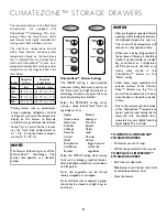
Page 35: ...th ClimateZoneTM Technology This technology allows the temperature within each drawer to be precisely controlled at optimal levels for storing meats fresh produce and fruit or citrus fruits The electronic temperature control within these drawers provides preset temperatures based on the food group that is selected The actual temperature within each ClimateZoneTM drawer is displayed electronically ...

Page 36: ...in until the bar rest in slot on underside of drawer front Close the drawer ClimateZoneTM Bulb Replacement There is a T8 40 watt bulb located behind each ClimateZone drawer Replacement bulbs are available from your dealer MCS part number 61008236 Note The ClimateZoneTM drawers power must be turned off at the main power switch before changing the bulb TO REPLACE THE BULB BEHIND THE UPPER CLIMATEZON...

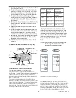
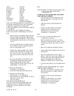
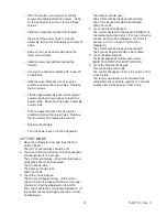
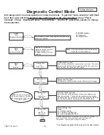
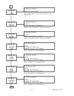
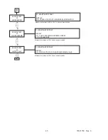
Page 37: ...uce keypads simultaneously for 5 seconds The LCD should display 88 and be illuminated All keypads should be illuminated The fan should stop The damper should close Wait 7 seconds 3 Touch the Citrus Keypad The fan should begin turning If the control cannot monitor the fans performance for proper function an F will be displayed on the LCD The control will test for the heater installation If the heat...

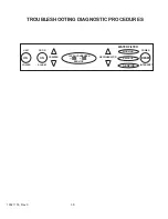
Page 38: ...16021730 Rev 0 38 TROUBLESHOOTING DIAGNOSTIC PROCEDURES INTERRUPT 88 88 ON WATER FILTER SERVICE POWER RESET ON SERVICE UNIT DOOR POWER ALARM FREEZER REFRIGERATOR CLEAN CONDENSER REPLACE WORKING ...

Page 39: ...heck for 12VDC on main control terminals JP11 3 2 Check for 26VDC on main control terminals JP11 3 1 If voltage is Pulsing in a repetitious manner there is probably an overload condition on the output side of the power supply Remove JP7 If Pulsing persists test JP7 harness for short circuits JP7 15 JP7 15 16 If Pulsing stops remove JP11 If Pulsing persusts replace power supply If Pulsing stops rep...

Page 40: ...will stop all normal functions and only operate the loads or sensors for each individual test period manually initiated PI Start and Stop Test Will display the software release version As found at top of page PI Set Un Set override Some performance characteristics of the unit are altered in high abient temperatures These performance characteristic changes can be overridden by setting this override...

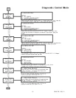
Page 41: ...mper will immediately begin closing This takes 7 10 seconds and will have to be observed by the service technician If test fails check for plus 12 VDC JP7 3 1 and plus 8 to 14 VDC JP7 3 2 If voltages exist at control check harness at fan terminals PI START STOP TEST DISPLAY PA TEST PASSED Hi FAN TOO FAST Lo FAN TOO SLOW Measure thermistor ohms at connector JP1 7 8 If open or short circuit check th...

Page 42: ...can be measured at JP8 1 JP13 1 PI START STOP TEST DISPLAY ON FAN SHOULD BE OPERATING During test line voltage can be measured at JP8 1 JP12 2 PI START STOP TEST DISPLAY ON FRESH FOOD LIGHTS SHOULD BE OPERATING During test line voltage can be measured at JP8 1 JP12 3 PI START STOP TEST DISPLAY ON FREEZER LIGHTS SHOULD BE OPERATING During test line voltage can be measured at JP8 1 9 PI START STOP T...

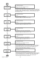
Page 43: ...BE OPERATING Display is in revolutions per second Range 42 50 average PI START STOP TEST DISPLAY SPEED FAN SHOULD BE OPERATING Ensure that temperature is in appropriate range PI START STOP TEST DISPLAY Will display fresh food thermistor temperature e g 13 72 is 137 2 degrees Ensure that temperature is in appropriate range PI START STOP TEST DISPLAY Will display fresh food thermistor temperature e ...

Page 44: ... START STOP TEST DISPLAY ON PRESS ACTUATOR TO ENERGIZE CUBE SOLENOID Filter in 26 V on JP13 2 remove filter 0 V on JP13 2 PI START STOP TEST DISPLAY in Filter in ou Filter out Verify 26 V on JP13 1 remove By Pass Verify 0 V on JP13 1 PI START STOP TEST DISPLAY in By Pass in ou By Pass out If display does not change Verify communications by removing tape from FF door switch HPSC s should light PI S...

Page 45: ... when actuator pushed PI START STOP TEST DISPLAY ON PRESS ACTUATOR TO ENERGIZE AUGER MOTOR Measure line voltage at JP8 1 6 when actuator pushed PI START STOP TEST DISPLAY ON PRESS ACTUATOR TO ENERGIZE WATER VALVE Measure line voltage at JP8 1 8 when actuator pushed PI START STOP TEST DISPLAY ON CHUTE SOLENOID ENERGIZES PRESS PI TO DE ENERGIZE ...

Page 46: ...A 1 ...

Page 47: ...Form No A 05 02 Part No 111405 1 MCS p n 61005583 Litho U S A 2002 Maytag Appliances Sales Co U S E R G U I D E ...

Page 48: ...298 USA and Canada Mon Fri 8am 8pm Eastern Time Internet http www jennair com For service and warranty informa tion see page 25 TABLE OF CONTENTS Welcome 1 Safety Instructions 2 Installation 3 Machine Compartment 4 Electronic Control Center 5 6 Fresh Food Compartment 7 ClimateZone Storage Drawers 8 9 Door Storage 9 Freezer Compartment 10 Automatic Icemaker 11 Automatic Ice Water Dispenser 12 Water...

Page 49: ... of explosive fumes Children should not climb hang or stand on the shelves of this refrigerator To prevent the unit from tipping for ward and to provide a stable installa tion the unit must be secured in place with the anti tip device See separate installation instructions provided with this refrigerator WARNING This ap pliance is designed to operate on a normal 115 volt 15 amp 60 cycle line There...

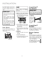
Page 50: ...ewalls 2 While depressing the front catches raise the shield up to the bottom of the control panel 3 Release the catches so they rest above the back edge of the control panel bottom TO REMOVE 1 Depress the catches at the front of the shield 2 Swing the shield downward 3 Lift the plastic hooks from the screws and pull the shield straight out IMPORTANT TheAir Diverter must be installed cor rectly to...

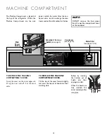
Page 51: ...h see page 6 The Machine Compartment is located at the top of the refrigerator Within the Machine Compartment are the main power switch the water filter the con denser and a switch to change the elec tronic control from Fahrenheit to Celsius Follow by inserting the bottom set of hooks into their appropriate slots When the hooks are fully inserted the cover securely settles into place TO REPLACETHE...

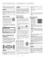
Page 52: ... changing light bulbs cleaning or serv icing this refrigerator INITIAL TEMPERATURE SETTINGS Temperatures are preset at 37 F 3 C in the fresh food compartment and 0 18 C in the freezer compartment The display will show the average compartment tem peratures based on several measurement points within the compartment The electronic control center is located at the top of the fresh food compartment NOT...

Page 53: ...es reached when the power was out Touch the RESET pad to enable this feature The RESET pad will illuminate After a power outage or interruption touch the RESET pad once to resume displaying the current compartment temperature The RESET pad will continue to be illuminated and enabled Touching the RESET pad a second time will turn off this function and the pad will not be illuminated NOTE Frozen foo...

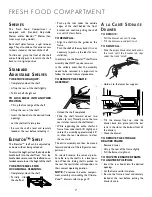
Page 54: ...items stored at the rear of the shelf To slide out grasp the front of the shelf and pull Gently push in to return the shelf back to its original position STANDARD ADJUSTABLE SHELVES TO REMOVE OR ADJUST Completely unload the shelf Lift up the rear of the shelf slightly Pull the shelf straight out TO LOCK SHELF INTO ANOTHER POSITION Tilt up the front edge of the shelf Lift up the rear of the shelf I...

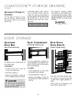
Page 55: ...etting when storing a mixed load of fresh fruits and vegetables such as Apples Broccoli Green onions Asparagus Nectarines Kiwi fruit Radishes Spinach Cabbage Celery Romaine Leeks Carrots Cherries Herbs Lettuce Strawberries bagged pre cut Cauliflower salads and Peaches vegetables Select the CITRUS setting when storing fruits such as oranges grapefruit lemons limes pineapple cranberries watermelons ...

Page 56: ...ine can be moved to other locations on the fresh food door TO MOVE Lift the compartment up until it clears the retainers on the door liner Pull the compartment straight out Reverse this procedure to secure the compartment into another position on the door DROP DOWN DOOR BASKETS Freezer Compartment Drop down door baskets provide conve nient storage for items that tend to shift or slide such as bagg...

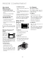
Page 57: ... on the frame Push the shelf all the way back It is not necessary to push up the tabs for rein stallation In ordinary use the Elevator shelf frame assembly does NOT require removal In the unlikely event that the assembly needs removal it is important to follow the correct removal procedure See page 7 WIRE FREEZER BASKETS To load or retrieve items from a freezer basket pull the drawer for ward TO R...

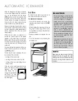
Page 58: ...nd taste stale Empty the ice storage bin periodically and wash it in luke warm water Rinse and dry thoroughly ICE BIN To check the ice level or gain access to the ice bin lift the door on the bin TO REMOVE THE BIN Turn off the icemaker by moving the icemaker wire lever arm up to the OFF position While holding the top edge of the ice bin grasp the lower edge of the ice bin and pull down to release ...

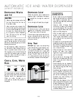
Page 59: ...for clean up It is recommended to clean the spill area occasionally to prevent mineral deposits ICE AND WATER DISPENSINGTIPS Some crushed ice may be dispensed even though cubed ice was selected This happens occasionally when a few cubes are accidentally channeled into the crusher Likewise when changing from crushed ice to cubes some crushed ice may be dispensed This may also happen if irregular si...

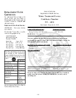
Page 60: ... for more than 2 weeks the filter should be replaced when the refrigerator is put back into service SPECIAL NOTICES It is essential that operation maintenance and filter replacement requirements be carried out as scheduled This product is for cold water use only Do not use with water that is microbio logically unsafe or of unknown quality without adequate disinfection before or after the system Sy...

Page 61: ...dor Yes Chlorine Class 1 Std 42 Yes Turbidity Std 53 Yes Particulate Std 42 Yes Class I Cyst Std 53 Yes Lead Std 53 Yes Capacity 416 gal 1574 L Function Chemical Mechanical NSF State of California Department of Health Services Water Treatment Device Certificate Number 99 1408 Date Issued December 14 1999 Trademark Model Designation Replacement Elements Maytag PuriClean UKF 7002 AXX UKF 7002 AXX Ma...

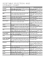
Page 62: ... freeze leftovers immedi ately Perishable food should never be allowed to be out at room temperature for greater than 2 hours total Store leftovers in clean shallow tightly covered containers The core of dense large pieces of meat and poultry or deep pots of soup and stew take longer to reach a safe storage temperature Shallow containers allow food to cool thoroughly more quickly Cut large cuts of...

Page 63: ...fter harvest Mushrooms should be plump firm and free of spots Choose well shaped compact heads Leaves should be dark maroon red with white veins Look for bright color with well formed roots and crisp white flesh Tops should be green and fresh Look for deep green coloring Avoid spinach that is yellowing wilted or has long stems Good quality sprouts should be brightly colored with a crisp texture Av...

Page 64: ... for its size Choose pieces that are free of bruises and blemishes Mangoes that are ripe will give to gentle pressure Look for fruit that is orange yellow between areas of red without any green Skin should be smooth and unblemished Choose firm fruit that is heavy for its size Avoid any with soft spots or white mold at the ends It is normal for ripe oranges to have a slight greening A papaya should...

Page 65: ...lemishes or growth cracks Watermelon should be ripe upon purchase they do not ripen after harvest Indicators that it was picked after it ripened include a dull rind dried stem and a yellowish underside where the melon touched the ground A ripe watermelon will also produce a distinct hollow sound when thumped If the rind is shiny and is white pale green or light yellow underneath it is immature STO...

Page 66: ...s located behind the electronic control panel at the top of the compartment Lower the light shield Replace the burned out bulb s with standard A15 40 watt appliance bulb s Available from your dealer part number 31956 After replacing the bulb s push the light shield up into its orig inal position LOWER FRESH FOOD COMPARTMENT There is aT8 40 watt bulb located behind each ClimateZone drawer Replace m...

Page 67: ...wer cords To reconnect the upper assembly power cords align the properly matching terminals and snap the power cords back together Push the assembly back into its original position and align the screw holes Replace the two screws and then replace the glass shelf Replace the air diverter strip Replace the drawers Turn the power back on to the refriger ator LOWER FREEZER COMPARTMENT Turn the power o...

Page 68: ...ses AIRFLOW SOUNDS There are a number of fans in the refrigerator that make airflow sounds when in operation The freezer fan circulates cool air throughout the refrigerator The refrig erator circulating fan helps keep that com partment s temperature more uniform The condenser fan on top of your refrigerator is utilized to remove the heat generated by the refrigeration system Lastly the Climate Zon...

Page 69: ... Do not use excessive amounts of cleaners or spray directly on the panel Do not use other cleaning sprays abrasive cleaners or large amounts of water on the panel Door Gasket Detergent and water or baking soda and water Use 1 2 tablespoons baking soda per quart of water Wring out excessive water from sponge or cloth when cleaning around controls lights or electrical parts Interior and Detergent an...

Page 70: ...DRAWERS Food not wrapped properly Hot humid weather NO TEMPERATURE READOUT IN THE CLIMATEZONE DRAWER DISPLAY The Normal Cold setting has been chosen CLIMATEZONE TEMPERATURE READOUT IS NOT WITHIN TARGET RANGE For best results refrigerator and freezer controls should be left at the factory settings see page 5 After drawer openings the addition of a new load or changing settings the readout may vary ...

Page 71: ... cm Width Models Shelving System Refrigerator Sealed Glass Shelf CJS423SSWA Refrigerator Compartment Refrigerator Elevator Shelf CJS423ESWA Refrigerator A la Carte Storage Drawer CJS423STWA Interior Door System Full width Dairy Compartment CJS424PDSA Refrigerator Adjustable Door Bin CJS424POSA 42 106 7 cm Width Models Shelving System Freezer Adjustable Storage Shelf CJS422SSWA Freezer Compartment ...

Page 72: ...B 1 Appendix B ...

Page 73: ... water supply and the copper tubes have been flushed until the water runs clear Reverse Osmosis Remove the water inlet connector from the Yellow valve and attach to the Blue valve Assure that the water filter bypass plug is in place See Fig 3 Disconnect wires from Yellow Valve Installation Instructions Fig 1 48 121 9 47 1 2 120 7 42 106 7 41 1 2 105 4 24 60 96 3 1 2 8 89 3 7 62 6 15 24 48 121 9 42...

Page 74: ... unit front to back and side to side This is to prevent tipping of the unit See Fig 7 Install the kickplate Locate the main power switch in the machine compartment and toggle the switch On Install the grille panel 3 8 Rear Leveler Front Leveler Kickplate 3 Phillips Screws GRILLE PANEL MAIN POWER SWITCH OR 3 8 Fig 2a Fig 2b Uncrating the Unit Uncrate the unit Remove the lower shipping bolts and bra...

Page 75: ...e the adhesive side of the packaging tape on the magnetic backed molding to pull it away from door Fig 8a Remove the screws with a phillips screwdriver Fig 8b Slide the backer panel into position The backer panel needs to be under the trim Install the handle Replace the molding in the channel and reset the magnetic backed molding To install the backer panel on the grille remove the screws on the t...

Page 76: ...d the door trim in place are accessible Remove screws and slide out door trim Close door and insert replacement panel Reinsert Torx screw and reinstall door trim Spill Tray Grille One piece Overlay Frame Panel Installation See Owner Manual for switching OFF O the unit Reference Fig 9 for door panel removal and installation With panels removed reattach hinge trim Lift slide out Spill Tray grille an...

Page 77: ... to top of panel D Bottom of dispenser cutout to top of panel E Left of dispenser cutout width F Right of dispenser cutout width Inches Cm 69 1 8 175 6 16 7 16 41 75 21 3 16 53 82 34 13 16 88 42 2 1 16 5 24 2 1 4 5 72 42 Wide Cabinet Inches Cm 69 1 8 175 6 18 11 16 47 47 21 3 16 53 82 34 13 16 88 42 2 3 16 5 56 4 3 8 11 11 48 Wide Cabinet Inches Cm 69 1 8 175 6 17 5 16 43 97 20 5 8 52 39 35 7 16 9...

Page 78: ...agnetic backed molding See fig 8a Drill 3 holes through vertical frame into cabinetry Where applicable approx location Installing Side Panels Optional side panels need to be 1 4 inch thick Slide panel into position and secure with screws indicated by the shaded area Fig 11a A 3 16 inch batten is required between the cabinet and side panel Fig 11b A 1 2 inch thick by 10 1 4 inch tall batten is requ...

Reviews: