background image

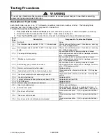
Testing Procedures 


!

WARNING


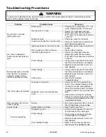
To avoid risk of electrical shock, personal injury or death; disconnect power and gas to oven before servicing, 
unless testing requires power and/or gas. 

18 16022089 

©2005 Maytag Services 


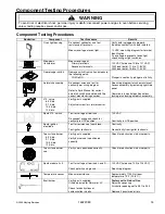
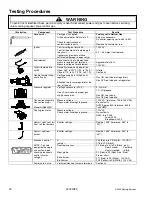
Component Test 

Procedure 

Results 

Control Panel Assembly 

Closed circuitry resistance  
(defined as continuity): 

1350 – 2250 

 for Cancel pads 1 & 20 

1275 – 2125 

 for Cancel pads 2 & 19 

320 – 2200 

 for all other pads 

Open circuitry resistance: 

Greater than 10 M


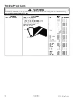
Pin 20

Pin 1


Pad


Cancel 


Clock 
Quick Preheat 
Bake 
Broil 
Keep Warm 
Convect Warm 
Convect Roast 
Cook Time 
Stop Time 
Clean 
Proofing 
Drying 
Meat Probe 
Vent Fan 
Auto Set 
Timer 1 
Timer 2 
Oven Light 

Trace 

7 & 8 
14 & 15 
10 & 14 
6 & 7 
6 & 8 
5 & 6 
4 & 5 
4 & 6 
3 & 4 
3 & 6 
1 & 2 

or 

1 & 19 

or 

2 & 20 

or 

19 & 20 
13 & 14 
16 & 18 
15 & 16 
16 & 17 
12 & 13 
6 & 10 
3 & 18 
10 & 18 
14 & 18 
15 & 18 
8 & 10 
9 & 10 
6 & 18 
11 & 12 
17 & 18 
12 & 14 
10 & 12 
10 & 11 

Measurement

Continuity 
Continuity 
Continuity 
Continuity 
Continuity 
Continuity 
Continuity 
Continuity 
Continuity 
Continuity 
Continuity 
Continuity 
Continuity 
Continuity 
Continuity 
Continuity 
Continuity 
Continuity 
Continuity 
Continuity 
Continuity 
Continuity 
Continuity 
Continuity 
Continuity 
Continuity 
Continuity 
Continuity 
Continuity 
Continuity 
Continuity 
Continuity


Summary of Contents for JGS8750ADB

Page 1: ...specific models This manual includes but is not limited to the following Service This manual is to be used by qualified appliance technicians only Maytag does not assume any responsibility for property damage or personal injury for improper service procedures done by an unqualified person JGS8750ADB S W JGS8850ADB Q S W Gas Slide In Range ...

Page 2: ... WARNING To avoid risk of severe personal injury or death disconnect power before working servicing on appliance to avoid electrical shock To locate an authorized servicer please consult your telephone book or the dealer from whom you purchased this product For further assistance please contact Customer Service Support Center CAIR Center Web Site Telephone Number WWW JENNAIR COM 1 800 536 6247 CAI...

Page 3: ...en Control Testing Procedures 17 Relay Logic 19 Quick Test Mode 20 Description of Fault Codes 21 Disassembly Procedures RemovingandReplacingRange 22 Top Burner 22 MaintopAssembly 22 Shut offValve 22 Top Burner Lower Assembly 22 Manifold and Top Burner 22 Regulator 22 GasValve 23 Bake Burner and Ignitor 23 Broil Burner and Ignitor 23 BroilElement 23 Infinite Switch 23 Back Panel 23 Cooling Fan 23 M...

Page 4: ...uires it 3 Checking for gas leaks Never check for leaks with any kind of open flame Soap and water solution should be used for this purpose Apply solution to suspected area and watch for air bubbles which indicates a leak Correct leaks by tightening fittings screws connections applying approved compound or installing new parts Recognize this symbol as a safety precaution WARNING If the information...

Page 5: ...al injury Wear proper apparel Loose fitting or hanging garments should never be worn when using oven Flammable material could ignite if brought in contact with flame or hot oven surfaces which may cause severe burns Never use range for warming or heating a room This may cause burns injuries or a fire Do not use water on grease fires Do not let grease or other flammable materials collect in or arou...

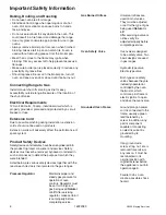
Page 6: ...e product to protect consumer and servicer Safety devices must never be removed bypassed or altered in such a manner as to defeat the purpose for which they were intended Listed below are various safety devices together with the reason each device is incorporated in the gas ranges Pressure Regulator Maintains proper and steady gas pressure for operation of oven controls Regulator must be set for t...

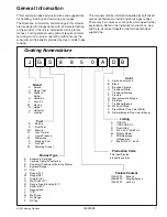
Page 7: ... 8 5 0 A D B Brand A Amana C Magic Chef G Graffer Sattler H Hardwick J Jenn Air M Maytag N Norge U Universal Y Crosley Product Type A Accessory Cartridge C Cooktop Updraft Countertop D Downdraft Cooktop or Warming Drawer E Eyelevel Range G Grill L Range 20 M Range 36 P Drop In 24 Q Wall Oven 27 R Range Free Standing 30 S Slide In 30 T Range Hood V OTR W Wall Oven Y RV Range Z RV Top Fuel B Butane ...

Page 8: ...r product inCanada call 1 866 587 2002 or visit the Web Site at www jennair com When contacting provide product information located on rating plate Record the following Model Number ___________________ Manufacturing Number ___________________ Serial or S N Number ___________________ Date of purchase ___________________ Dealer s name and address ___________________ Service Keep a copy of sales rece...

Page 9: ...CTION may be made to a properly grounded two prong wall receptacle by the use of a UL listed adapter available at most hardware stores Larger slot on adapter must be aligned with larger slot in the wall receptacle to provide proper polarity WARNING Attaching adapter ground terminal to wall receptacle cover screw does not ground appliance unless the cover screw is metal and not insulated and wall r...

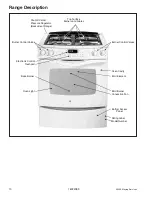
Page 10: ... Bake Burner Bottom Access Panel Convection Fan Shut off Valve Pressure Regulator Backside of Range Electronic Control Touchpad Top Surface Burners and Grates Oven Light Model Number Rating Label Burner Control Valves Burner Control Valves Oven Cavity Broil Element ...

Page 11: ...inst appropriate wiring diagram Verify all terminals and connections are correct and tight Check module according to testing procedures information Clean electrode or burner cap Replace electrode No spark or only random spark at one ignitor Check for cracked ignitor or pinched ignitor wire Poor continuity to burner cap Bad ground connection or lack of continuity to ground or ignitor Cracked or bro...

Page 12: ...is not tripped Replace household fuse but do not fuse capacity Broil burner shuts off shortly after the start of self clean operation Bake and broil functions operate normally Power outage Control Error Verify power is present at unit Verify that the circuit breaker is not tripped Replace household fuse but do not fuse capacity See Control Systems Troubleshooting Fan motor does not operate No powe...

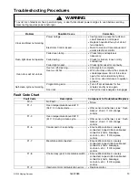
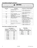
Page 13: ...ow cool air on door latch area to quicken process Self clean cycle not working Programming error Door lock Turn off circuit breaker for five minutes and try oven again Verify door lock energizes engages Fault Code Chart Fault Code Description Component to Troubleshoot Replace F0 0 No Fault None F1 1 Oven temperature above 650 F 343 C in bake mode Ohm sensor and harness see Oven Sensor chart If OK ...

Page 14: ...ace control F3 1 Open or shorted sensor Ohm sensor and harness F8 Shorted meat probe Check probe jack and harness probe jack harness If OK check meat probe see Meat Probe chart F9 1 Oven door will not lock Check wire connections If OK replace motorized door lock F9 2 Oven door will not unlock Check wire connections If OK replace motorized door lock F9 3 Oven door status is both locked and unlocked...

Page 15: ...manufacturing number See wiring diagram for schematic layout Access assembly by removing right side panel Common is in neutral position unless locking or unlocking autolatch assembly 270 valve 6 5 K btu 9 1 K btu 10 5 K btu 12 K btu Verify gas is supplied Adjust set screw for simmer control Spark 270 switch Test for voltage at terminals Disconnect wiring and check for continuity in LITE position 1...

Page 16: ... Attached to pressure regulator at the rear of the unit Gas ON red tab up at regulator Gas OFFred tab down at regulator Pressure regulator Verify gas pressure W C P If on LP service verify proper gas supply conversion 5 Natural 10 LP propane Gas ON red tab up Gas OFFred tab down Convection assembly Convection motor Model JGS8850AD Measure voltage Check motor windings to ground 120 VAC tolerance 10...

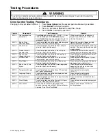
Page 17: ...hour shutoff allowing the oven to operate indefinitely EOC II Sound Level Beeper Volume Press Setup Options and the Sound Level pad also the 3 pad simultaneously Press Autoset to select setting I lowest through IIIIIIII 8 highest EOC II 24 Hour Clock Press Setup Options and the 12 24 Hour Clock pad also the 4 pad simultaneously Press Autoset to select option 12 hour time or 24 hour time EOC II Scr...

Page 18: ...k Quick Preheat Bake Broil Keep Warm Convect Warm Convect Roast Cook Time Stop Time Clean Proofing Drying Meat Probe Vent Fan Auto Set Timer 1 Timer 2 Oven Light Trace 7 8 14 15 10 14 6 7 6 8 5 6 4 5 4 6 3 4 3 6 1 2 or 1 19 or 2 20 or 19 20 13 14 16 18 15 16 16 17 12 13 6 10 3 18 10 18 14 18 15 18 8 10 9 10 6 18 11 12 17 18 12 14 10 12 10 11 Measurement Continuity Continuity Continuity Continuity ...

Page 19: ...NVECTION FAN HI SPEED CONVECTION FAN LO SPEED BROIL ELEMENT OVEN LIGHT IDLE r r r r r BAKE PREHEAT O r r r O BAKE O r r r BROIL PREHEAT r O r r O BROIL r O r r O CLEAN PREHEAT O r r r r r CLEAN r O r r r r KEEP WARM PREHEAT O r r r O KEEP WARM O r r r CONVECT BAKE QUICK PREHEAT O r r O O CONVECT BAKE PREHEAT O r r O O CONVECT BAKE O r r O QUICK PROOFING PREHEAT O r r O r QUICK PROOFING O r r O r S...

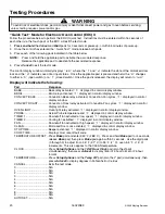
Page 20: ...d 1 displayed in control display window CONVECT BAKE Convection Bake relay activated Convection Fan cycles 1 displayed in control display window CONVECT ROAST Convection Roast relay activated Convection Fan cycles 1 displayed in control display window OVEN LIGHT Oven light relay activated 1 displayed in control display window PROBE Actual Probe temperature and 1 displayed in control display window...

Page 21: ...ector shorts breakage corrosion etc If OK replace control F1 7 Membrane disconnected Ensure ribbon cable is securely connected inspect ribbon cable and connector shorts breakage corrosion etc If OK replace control F1 8 Shorted key pad in membrane switch Ensure ribbon cable is securely connected inspect ribbon cable and connector shorts breakage corrosion etc If OK replace control F1 9 Internal con...

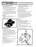
Page 22: ...Ignitor Venturi Venturi Burner Valve Spark Module Bracket Burner Base Burner Cap Gas Crossover Removing and Replacing Range 1 Remove power from unit 2 Disconnect downdraft blower motor and remove flex ducting to the blower and range select models NOTE To avoid countertop damage do not move range forward until range has been raised enough to clear all cabinetry 3 Pull the range forward out of the c...

Page 23: ...ator lights rocker switches and electronic control clock as necessary and transfer to the new control panel 6 Reverse procedure to reinstall control panel Gas Valve NOTE Removal of range from installation position is required 1 Disconnect power before servicing 2 Remove range from installation position see Move and or Replacing Range procedure 3 Remove screws securing bottom rear access panel to c...

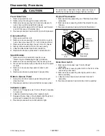
Page 24: ...e new bulb and decreasing life of the bulb do not touch new bulb with bare hands or fingers Hold with a cloth or paper towel NOTE Proceed with the following steps for oven light socket removal 5 Remove unit from installation position see Removing and Replacing Range procedure 6 Disconnect or unplug the power cord leading from unit to fuse box or junction box depending on unit 7 Carefully displace ...

Page 25: ... Disconnect and label wire connections from the spark module 4 Remove screws securing spark module to unit chassis 5 Replace and reverse procedure to reassemble Bottom Access Panel 1 Grasp top of bottom access panel and gently pull down and out 2 Reverse procedure to reinstall bottom access panel Indicator Lights 1 Remove control panel see Control Panel procedure for removal 2 Label and disconnect...

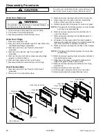
Page 26: ...einstall oven door hinge Door Disassembly 1 Remove oven door see Oven Door Removal procedure 2 Place door on a protected surface 3 Remove screws securing bottom trim to oven door 4 Slide outer oven door glass and trim towards the bottom of the oven door and remove 5 Detach right and left trim pieces for outer door glass NOTE Proceed with the following steps for door handle and inner door disassemb...

Page 27: ... 2005 Maytag Services 16022089 A 1 Appendix A ...

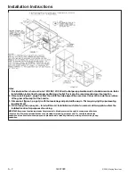
Page 28: ...dle 3 Dimension L figure 3 page 3 is with the leveler legs adjusted all the way in This may vary slightly upon leveling leg adjustment 4 Do not use grout epoxy etc to install this unit Installation must allow for removal of this appliance from the installed location for purposes of servicing IMPORTANT Because of continuing product improvements Maytag reserves the right to change specifications wit...

Page 29: ...r recreational vehicles must conform with state or other codes or in the absence of such codes with the Standard for Recreational Vehicles ANSI A119 2 latest edition In Canada the range must be installed in accordance with CAN CSA Z240 6 2 Electrical Requirements for R V s CSA Standard CAN CSA Z240 RV Series and Section Z240 4 2 Installation Requirements for Propane Appliances and Equipment in R V...

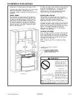
Page 30: ...et to the floor with the two screws provided Proceed to STEP 3 2 Wall Locate the center of the two holes identified in figure 5 as HOLES FOR WALL Drill an angled 1 8 pilot hole in the center of each hole as shown in figure 6 A nail or awl may be used if a drill is not available Secure the ANTI TIP bracket to the wall with the two screws provided as shown in figure 6 Proceed to STEP 3 B Cement or C...

Page 31: ...M OF 14 INCHES WATER COLUMN 0 5 POUNDS PER SQUARE INCH P S I LIQUEFIED PETROLEUM L P PROPANE GAS SUPPLY LINE MUST HAVE A L P GAS PRESSURE REGULATOR INLET PRESSURE TO THIS APPLIANCE SHOULD BE REDUCED TO A MAXIMUM OF 14 INCHES WATER COLUMN 0 5 P S I INLET PRESSURES IN EXCESS OF 0 5 P S I CAN DAMAGE THE APPLIANCE PRESSURE REGULATOR AND OTHER GAS COMPONENTS IN THIS APPLIANCE AND CAN RESULT IN A GAS LE...

Page 32: ...M OF 14 INCHES WATER COLUMN 0 5 POUNDS PER SQUARE INCH P S I LIQUEFIED PETROLEUM L P PROPANE GAS SUPPLY LINE MUST HAVE A L P GAS PRESSURE REGULATOR INLET PRESSURE TO THIS APPLIANCE SHOULD BE REDUCED TO A MAXIMUM OF 14 INCHES WATER COLUMN 0 5 P S I INLET PRESSURES IN EXCESS OF 0 5 P S I CAN DAMAGE THE APPLIANCE PRESSURE REGULATOR AND OTHER GAS COMPONENTS IN THIS APPLIANCE AND CAN RESULT IN A GAS LE...

Page 33: ... 2005 Maytag Services 16022089 B 1 Appendix B ...

Page 34: ...B 2 16022089 2005 Maytag Services Use Information ...

Page 35: ... 2005 Maytag Services 16022089 B 3 Use Information ...

Page 36: ...B 4 16022089 2005 Maytag Services Use Information ...

Page 37: ... 2005 Maytag Services 16022089 B 5 Use Information ...

Page 38: ...B 6 16022089 2005 Maytag Services Care Information ...

Page 39: ... 2005 Maytag Services 16022089 B 7 Care Information ...

Page 40: ...B 8 16022089 2005 Maytag Services Care Information ...

Page 41: ... 2005 Maytag Services 16022089 C 1 Appendix C ...

Page 42: ...re regulator must be converted to regulate LP gas If converting from LP gas to natural gas the appliance pressure regulator must be converted to regulate natural gas To convert the appliance pressure regulator from one gas to another do either 1 2 or 3 below Your unit will be equipped with one of the three appliance pressure regulator types shown below 1 Remove the cap push down and turn counter c...

Page 43: ... cause the flame to lift or blow off the burner when cold NOTE Correctly adjusted sealed burners can have flames that will lift or blow without a pot over the burner These should be adjusted with a pot in place 2 From LP Propane Gas To Natural Gas a Change the appliance pressure regulator from LP to natural setting See figures 10 11 or 12 b Screw the burner orifice hoods away from the pins See fig...

Page 44: ...OTE When burner heads are removed for cleaning do not spill liquids through the holes in the burner base HOW TO REMOVE RANGE FOR CLEANING AND SERVICING Follow these procedures to remove appliance for cleaning or servicing 1 Shut off gas supply to appliance 2 Disconnect electrical supply to appliance if equipped 3 Disconnect gas supply tubing to appliance 4 Slide range forward to disengage range fr...

Reviews: