background image


Product specific safety precautions 


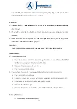
This  equipment  is  designed  be  operated  by  qualified  personnel.  It  should  only  be  operated  after 

reading and understanding the safety warnings and operating procedures in this instruction manual. 

1.


Do not smoke near this equipment. 

2.


Firework  is  strictly  prohibited  during  operation,  keep  away  from  heat,  high  voltage,  flammable 

and explosive place 

3.


Use in a well ventilated area.


4.


When leaks are found in the equipment or hoses, immediately turn the air pressure off and repair 

the leaks. 

5.


Once leakage is found in the hose or other components during operation, turn off air compressor 

immediately, conduct a detailed inspection and proceed with troubleshooting. 

6.


Do  not  exceed  the  recommended  operating  air  pressure.  This  could  damage  equipment.  See 

specification on Page 5.


7.


Keep a type ABC fire extinguisher nearby in case of fires.


8.


Always protect your skin and eyes from contact with oil and solvents.


9.


Do  not  start  engine  during  the  time  of  oil  extraction.  Otherwise  it  will  cause  the  damage  of 

extraction probes and injuries of people.


10.


Be careful for the oil extracted out from the vehicle, as temperature of oil is high, always between 

40~60


11.


Used oil should be properly disposed or recycled. Please contact with your local waste liquid/solid 

authority for information on recycling. 


Summary of Contents for JA1041OD

Page 1: ...1 Pneumatic Oil Extractor Operational Manual Model No JA1041OD ...

Page 2: ...you are tired 7 Check for damaged parts Before using any tool any part that appears damaged should be carefully checked to determine that it would operate properly and perform its intended function Check for alignment and binding of moving parts any broken parts or mounting fixtures and any other condition that may affect proper operation Any part that is damaged should be properly repaired or rep...

Page 3: ... other components during operation turn off air compressor immediately conduct a detailed inspection and proceed with troubleshooting 6 Do not exceed the recommended operating air pressure This could damage equipment See specification on Page 5 7 Keep a type ABC fire extinguisher nearby in case of fires 8 Always protect your skin and eyes from contact with oil and solvents 9 Do not start engine du...

Page 4: ...ical engine oil lubricants as well as temporary storage Brake fluid gasoline diesel and other liquid contains methanol and ketoses or flammable is strictly prohibited Specification Functions Remove and extract waste fluids or oil out from engine and etc with flexible PVC tube and robust CU probe Power from compressed air Air Inlet Pressure 6 8bar 87 116PSI Ejection pressure 0 6 0 8 bar 8 7 11 6PSI...

Page 5: ...n the oil tank with clock wise direction 3 Then screw the Fasten Nut fixed on the top of the tank with Cylinder Oil Tray 1 Open the carton to take out the oil tray check to see if there is any damage If so please contact with your distributor immediately 2 Pull out the lift pole and Screw the oil tray on with clock wise direction 3 Take out the cylinder connect it to the oil tank with ball valve h...

Page 6: ...f all valves BEFORE use 2 Connect the air compressor to the air inlet gradually turn on the air inlet ball valve for vacuumization 3 Gradually turn on the air inlet valve which equipped by customer himself for vacuum generation 4 When finger reaching to the MAX area on the vacuum gauge turn off the air inlet valve Estimated time for vacuum generation within 20 30seconds 5 Turn off air source after...

Page 7: ...e the pipe of air compressor 6 Now it is ready for extraction Notice Under a working condition without air source Please pump the tank with vacuum air before use Tips 1 Benefits for gradually and slowly turn on air inlet valve is for reducing air consumption and a quicker speed for vacuum generation 2 Benefits for vacuum generation of both cylinder and oil tank is fasting the speed of oil transfer...

Page 8: ...raction ball valve Fig 01 Place the machine in a flat ground to avoid sliding during operation Oil temperature higher than 80 C will cause seriously damage to the components in worst case it could bring to machine failure 5 Ejection Oil ejection from cylinder to underside oil tank 1 When the oil level reached cylinder STOP warning line please empty the cylinder with oil ejection 2 Turn on ball val...

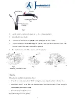
Page 9: ... 1 Lift the vehicle to proper height 2 Move the oil extractor below the car engine oil tray position right under the vehicle oil drain hole 3 Ensure ball valve is off 4 Open the wing valve by rotating it in anticlockwise direction vertical sitting as open 5 Open the mini ball valve release tank pressure 6 Waste oil is transfer from the oil tray to the oil tank 7 Tank Emptying When the oil retained...

Page 10: ...ure is over 35PSI 2 5kgs during ejection Trouble Shooting A Vacuum gauge don t work a Check the air pressure standard air pressure through air inlet valve should between 86 114PSI 6 8Bar Air consumption is 52 Gallons min 200L Min b Make sure all the valves are on the correct place c Check vacuum operator to tank seal B There is a figure showed on the vacuum gauge but the machine don t working and ...

Page 11: ... time ordinary one year please check the adapter of the probe for leakage Notes a Application for oil change with probe for metal probe big suction capacity 3 1L Min small suction capacity 0 8L Min for plastic probe the biggest one suction capacity 4 3L Min the smallest one 0 8L Min b If you work for suction oil for a long time please check the adapter O seals of the cylinders adaptors for leakage...

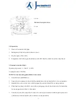
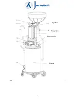
Page 12: ...12 FIG 3 2 Cylinder Locking ring Wing valve Oil tank ...

Page 13: ...13 ...

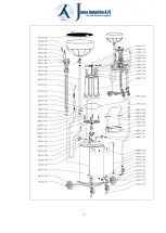
Page 14: ...HC97_048 Elbow connector male female 1 20HC97_015 handle 1 20HC97_049 Tool box 1 20HC97_016 inside hexagonal screw 1 20HC97_050 handle 1 20HC97_017 Locking ring 1 20HC97_051 hexagonal screw 2 20HC97_018 hexagonal screw 1 20HC97_052 Gasket 2 20HC97_019 O ring 2 20HC97_053 Handle set 1 20HC97_020 Oil cup 1 20HC97_054 Flat head hexagonal screw 2 20HC97_021 ejection hose 1 20HC97_055 Exhibit crotch 1 ...

Page 15: ...15 ...

Reviews: