background image

Jema Autolifte A/S Industrihegnet 2   4030 Tune   Denmark   Tel. (+45) 48180300   

[email protected]


www.jemaautolifte.dk


4.  DEMOUNTING TYRE 

Switch machine and air supply on. 

Pull  tyre  separator  lever  21  back,  insert  wheel  between  separator  arm  and  rubber  cushion  on  machine 
wall and move the arm to touch the tyre, close to wheel rim edge. 

BE CAREFUL NOT TO REST THE ARM AGAINST WHEEL RIM 

Holding  separator  arm  in  appropriate  position,  depress  tyre  separator  pedal  18  and  hold  it  until  the 
tyre  is  separated  from  wheel  edge.  If  necessary,  repeat  the  operation  at  several  points  of  wheel 
circumference.  Then  reverse  wheel  and  separate  in  the  same  way  tyre  from  wheel  rim  on  the  other 
side of the wheel. 


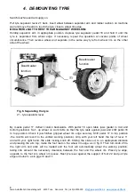
Fig 6. Separating the tyre 

21 - tyre separator lever 

By  means  pedal  17,  deflect  column  backwards.  With  pedal  16  open  table  jaws  (pedal  in  mid  and 
bottom  positions).  Set  -  up  wheel  on  work  table  so  that  the  tyre  rests  against  jaws  and  shift  pedal  16 
to  top  position.  Check  if  jaw  hitches  gripped  wheel  rim  edge  securely.  Shift  pedal  17  to  top  position 
-the  column  will  revert  to  the  vertical  working  position).  Grip,  with  your  left  hand,  the  top  of  lever  11 
and  with  your  right  hand,  the  slide  locking  knob  20.  Sliding  the  slide  out,  to  an  appropriate  distance 
and  pressing  the  arm  top,  make  the  foot  rest  on  the  wheel  rim  edge,  as  in  fig  9.  Then  turn  knob  20  to 
the  right  arm  and  slide  will  be  loaded  and  the  foot  will  automatically  adopt  the  working  position, 
taking  into  account  the  necessary  clearance  between  the  foot  and  the  wheel  rim.  Press  tyre  edge, 
opposite  to  the  foot  into  wheel  rim  recess.  Rest  tyre  lever  against  the  support  of  foot  22  and  pull  tyre 
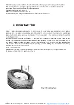
edge on bulb 23 - as in gigs 10 and 11. 

8  

Beadbreaker 
function 

Beadbreaker 
function 

Summary of Contents for DWB-8-E

Page 1: ...Jema Autolifte A S Industrihegnet 2 4030 Tune Denmark Tel 45 48180300 info jemaautolifte dk www jemaautolifte dk Tyre changer DWB 8 E Euro line OPERATING MANUAL ...

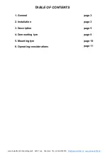
Page 2: ...2 4030 Tune Denmark Tel 45 48180300 info jemaautolifte dk www jemaautolifte dk TABLE OF CONTENTS 1 General page3 2 Installation page3 3 Description page5 4 Demounting tyre page8 5 Mounting tyre page10 6 Operating considerations page 11 ...

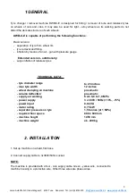
Page 3: ...un with pressure gauge Extended version additionally surge inflation of tubeless tyres 1 Set up machine on a hard flat base 2 Connect supply cable to 3x380V 50Hz socket NOTE The machine is provided with a four core supply cable Green yellow wire connected to machine housing is a protective wire Other three wires are phase wires TECHNICAL DATA tyre diameter range max tyre width wheel clamping on ma...

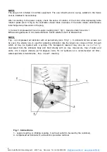
Page 4: ...essure 8 mm inside diameter Check whether oiler 5 is filled with oil NOTE Top up compressed air lubricator with oil periodically item 5 fig 1 In lubricator lid two screws can be seen the smaller one is used for adjusting lubrication rate the larger one closes oil filler through which oil may be injected with a syringe The transparent reservoir may also be c a r e f u l l y unscrewed from the lubri...

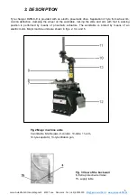
Page 5: ...ection clamping the wheel on the worktable locking the slide and arm with foot in working position is performed by means of pneumatic actuators The worktable is rotated by means of an electric motor Major machine units are shown in figs 2 3 4 and 5 Fig 2 Major machine units 7 worktable 8 table jaws 9 column 10 slide 11 arm 12 tyre separator 13 tyre inflation gun Fig 3 View of the back wail 6 Extra...

Page 6: ...ition Subsequent precision of pedal will stop jaw movements Press pedal gently to avoid its shifting to bottom position 3 bottom position full outward travel of jaws Subsequent precision of pedal shifts it into top position Column deflection pedal item 17 Have three working positions 1 top position column in working position vertical 2 mid position backward deflection of column to any distance how...

Page 7: ...ges separator Worktable rotation pedal item 19 Has three working position 1 mid position initial table drive disengaged 2 pressing the pedal engages clockwise rotation of table operating rotation release of pedal disengages rotation 3 lifting the pedal with your foot from mid position engages anticlockwise rotation of table 9 emergency rotation release of pedal disengages rotation Slide locking kn...

Page 8: ...17 deflect column backwards With pedal 16 open table jaws pedal in mid and bottom positions Set up wheel on work table so that the tyre rests against jaws and shift pedal 16 to top position Check if jaw hitches gripped wheel rim edge securely Shift pedal 17 to top position the column will revert to the vertical working position Grip with your left hand the top of lever 11 and with your right hand ...

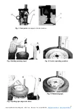
Page 9: ...ihegnet 2 4030 Tune Denmark Tel 45 48180300 info jemaautolifte dk www jemaautolifte dk Fig 7 Foot parts 22 support 23 bulb 24 shoe Fig 9 Foot in operating position Fig 8 Setting working head Fig 10 pulling tyre edge onto shoe 9 ...

Page 10: ...le and shift pedal 16 to top position Check whether jaw hitches gripped wheel rim edge securely Shift pedal 17 to top position the column will return to vertical operating position Grip with your left hand the top of lever 11 and with your right hand the slide locking knob 20 By moving slide outwards to an appropriate distance and pressing the top of the arm bring the foot to rest against wheel ri...

Page 11: ...un with pressure gauge or by means of automatic inflator description how to operate the inflator will be found in the latter part of these instructions Unload arm and slide with knob 20 Deflect column backwards with pedal 17 Open worktable jaws with pedal 16 and remove wheel from machine 6 OPERATING CONSIDERATIONS The worktable is driven by an electric motor through a worm gear lubricated with She...

Page 12: ...ed standards or other norms documents Basic concepts general principles for design Part 1 Basic concepts general principles for design Part 2 Generic emission standard residential commercial and light industry Generic emission standard industrial environment Generic immunity standard residential commercial and light industry Generic immunity standard industrial environment Safety distances to prev...

Page 13: ...ther norms documents Basic concepts general principles for design Part 1 Basic concepts general principles for design Part 2 Generic emission standard residential commercial and light industry Generic emission standard industrial environment Generic immunity standard residential commercial and light industry Generic immunity standard industrial environment Safety distances to prevent danger zones ...

Page 14: ...te A S Industrihegnet 2 4030 Tune Denmark Tel 45 48180300 info jemaautolifte dk www jemaautolifte dk Industrihegnet 2 4030 Tune Denmark Tlf 45 48180300 E mail info jemaautolifte dk Website http www jemaautolifte dk ...

Reviews:

Related manuals for DWB-8-E