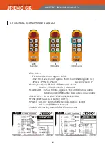
background image

17

JREMO 6K

Industrial radio remote controller

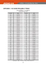
APPENDIX II : 447 & 173& 429 FREQUENCY TABLE

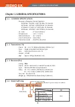
APPENDIX II : 447 & 173 & 429 FREQUENCY TABLE

CH. NO.

MHz

001

447.6000

002

447.6125

003

447.6250

004

447.6375

005

447.6500

006

447.6625

007

447.6750

008

447.6875

009

447.7800

010

447.7125

011

447.7250

012

447.7375

013

447.7500

014

447.7625

015

447.7750

016

447.7875

017

447.8000

018

447.8125

019

447.8250

020

447.8375

021

447.8500

022

447.8625

023

447.8750

024

447.8875

025

447.9000

026

447.9125

027

447.9250

028

447.9375

029

447.9500

030

447.9625

031

447.9750

032

447.9875

033

-

034

-

035

-

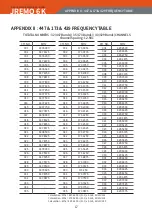
TOTATAL NUMBERS : 32 (447 Bands) / 35 (173 Bands) / 40 (429 Bands) CHANNELS

Channel Spacing : 12.5Kc

CH. NO.

MHz

001

173.0250

002

173.0375

003

173.0500

004

173.0625

005

173.0750

006

173.0875

007

173.1000

008

173.1125

009

173.1250

010

173.1375

011

173.1500

012

173.1625

013

173.1750

014

173.1875

015

173.2000

016

173.2125

017

173.2250

018

173.2375

019

173.2500

020

173.2625

021

173.2750

022

173.6250

023

173.6375

024

173.6500

025

173.5625

026

173.6750

027

173.6875

028

173.7000

029

173.7125

030

173.250

031

173.7375

032

173.7500

033

173.7625

034

173.7750

035

173.7875

Calculation : Mhz = 447.6000 + (N-1) x 0.125, 01≤N≤32

Calculation : Mhz = 173.0250 + (N-1) x 0.125, 01≤N≤35

Calculation : Mhz = 429.2500 + (N-1) x 0.125, 22≤N≤40

CH. NO.

MHz

001

429.2500

002

429.2625

003

429.2750

004

429.2875

005

429.3000

006

429.3125

007

429.3250

008

429.3375

009

429.3500

010

429.3625

011

429.3750

012

429.3875

013

429.4000

014

429.4125

015

429.4250

016

429.4375

017

429.4500

018

429.4625

019

429.4750

020

429.4875

021

429.5000

022

429.5125

023

429.5250

024

429.5375

025

429.5500

026

429.5625

027

429.5750

028

429.5875

029

429.6000

030

429.6125

031

429.6250

032

429.6375

033

429.6500

034

429.6625

035

429.6750

036

429.6875

037

429.7000

038

429.7125

039

429.7250

040

429.7375

Summary of Contents for JREMO 6K

Page 1: ...O M MANUAL JREMO 6K REMOTE CONTROL www jeico com ...

Page 2: ...y period from the date of delivery installation inspection shall be one calendar year Subject to confirming defects not caused by improper installation improper operation and or insufficient maintenance unauthorized modification ignorance of environmental specifications or improper interfacing irresistible forces such as war s strike s Act s of God and so on all such the defects shall be treated a...

Page 3: ... DIAGRAMS 08 CHAPTER 3 INSTALLATION FUNCTION SETTING 09 3 1 CAUTIONS FOR INSTALLATION 09 3 2 HOW TO INSTALL TRANSMITTER TX 10 3 3 HOW TO INSTALL RECEIVER RX 11 3 4 HOW TO START 12 CHAPTER 4 MAINTENANCE 13 4 1 Standard Operation 13 4 2 FUSES 13 CHAPTER 5 TROUBLESHOOTING 14 5 1 SELF DIAGNOSIS LED SIGNAL ERROR MESSAGE 14 5 2 LED Diagnosis 14 5 3 Troubleshooting 15 APPENDIX Ⅰ 433 BAND FREQUENCY TABLE ...

Page 4: ... not use After use switch off the main power of the equipment ex crane and confirm the receiver power off and then turn off the rotary key of the transmitter before pull out the key and store the key in an isolated area When not in use stay the transmitter in a safety area and do not allow an unauthorized to attempt to use it Equipment ex crane using this remote controller must have main relays li...

Page 5: ...easures C EMERGENCY MEASURES JREMO Series has designed for safety meeting with various kind of emer gencies and for self recovering Billions of different I D code Self Diagnoses super qualified and isolated protection against voltage surges and or inter feres etc are the basic integral functions for solving any unexpected accident or trouble in an emergency So when such an emergent function is det...

Page 6: ... Tx Power 6K 2 x 1 5 V Alkaline Batteries LR6 AA Size Type Single or Double Push Button Type Size 148 x 48 x 45 mm L x W x H Output 5mW Wgt Approx 185 gr Batteries Incl 1 3 Receiver Rx Casing RX2 Power AC110 440V or DC12 40V OPT AC48V DC 60V Type Remote ON Main Lamp Indication Ralay AC A Contact 250VAC 5A 125VAC 10A DC A Contact 24VDC 15A 120VAC 15A Size mm 90 x 152 x 105 Weight gr 950 Antenna Pow...

Page 7: ... a set Single P B 173 x 62 x 46 mm Approx 355 gr RX2 90 X 152 x 105mm Approx 1 350 gr Tx Rx FUNCTIONS MODEL NAMERECEIVER SIZE Standard Single P B JREMO 6K A RX2 16 Core Cable U D Creep Double P B JREMO 6K B RX2 18 Core Cable 6 Double P B JREMO 6K C RX2 16 Core Cable Single P B For D C JREMO 6K M RX2 12 Core Cable Tx Button Labelling can be in English Chinese Japanese Spanish or other languages upo...

Page 8: ...Locking system Y Stanby Standard EMS UP P B Main ON Start Option EMS UP North P B Main ON CABLE SPEC 0 75 Sq 600VAC approx 1 7M 16 CORE number cable Optional Single 4P B number 8 10 cable is not available RELAY SPEC A CONTACT 250VAC 5A 125VAC 10A FUSE 20MM Glass Fuse 1A F1 10A F2 POWER AC 100 440V 50 60Hz Free Volts Option AC48V DC 12 40V JREMO 6K M model Standard Rx Setting Auto off after 1 hour ...

Page 9: ...ane before installation and confirm it is under utmost safety condition 7 Do not try to install without gaining in skill for electrical circuit diagrams and operation circuits of equipment ex crane remote controller s func tions etc for avoiding an unexpected accident wrong functions etc 8 For avoiding any possible interferes install receiver far from motor and transducer as following illustration...

Page 10: ...re low Replace them all 2 batteries immediate ly and simultaneously with new ones D When not in use press down the EMS button for saving battery life as well as off the battery power and for safety as well 3 2 2 FUNCTION SETTING COPYING In case to change either Tx or Rx or modify functions its mating transmitter and receiver must be identical and set both at the same time for sure identification F...

Page 11: ...ools B Select a proper place for installation 1 Choose a safe area a visible area of receiver or antenna 2 Avoid a spark area ex motors relays magnet switches electric cables are likely generating sparks and interferes 3 Avoid high voltage and current area 4 Receiver is to be distanced at least 3cm from obstacles C Match receiver power 1 Check input power source and make sure to connect to the rig...

Page 12: ... Rx power and push down red EMS button of Tx H After off the power of Rx Tx connect all the remained functional each wire of Rx to a mating terminal of equipment ex crane 1 Confirm both circuit diagram of receiver and equipment ex crane are in sequence and connected correctly 2 Confirm ground is O K 3 Check and confirm again power source F Switch on receiver power by setting to remote at the selec...

Page 13: ...stops etc during working with both red and green light signalling B Press down the EMS button when every normal operation finished and or in any emergency situation might occur do the same at once C In case not in use for a long term operation take off all the batteries from tx for avoiding of any contamination and or unnecessary consump tion of battery power CHAPTER 4 MAINTENANCE 4 2 FUSES A A re...

Page 14: ...site CHAPTER 5 TROUBLESHOOTING 5 2 LED Diagnosis Causes LED Signals Measures Transmitter TX EMS Button not up Red Light Pull up EMS Button Push Button defect Red Flash Replace with new button s Encoder Module defect No Signal Replace with a new module Batteries Consumed No Signal Replace with new batteries Low Power Red Green Flashes Replace with new batteries Receiver RX Decoder defect Lamp Off R...

Page 15: ...Rf Module defect 3 Rx Antenna defect 4 Wrong Rx Power 5 Cable Short circuit 6 No Remote Positioned 7 Frequency Interferes 1 Replace with new antenna 2 Replace with new Rx Rf 3 Replace with new antenna 4 Correct Rx power source 5 Change with new Cable 6 Set to Remote Position 7 Set to other channel Rx Lamp ON Not Working 1 Cable Short circuit 2 No Remote Positioned 3 Frequency Interferes 4 Relay de...

Page 16: ...33 675 027 433 700 028 433 725 029 433 750 030 433 775 031 433 800 032 433 825 033 433 850 034 433 875 035 433 900 TOTAL NUMBERS 70 CHANNELS Channel Spacing 25 Kc CH NO MHz 036 433 925 037 433 950 038 433 975 039 434 000 040 434 025 041 434 050 042 434 075 043 434 100 044 434 125 045 434 150 046 434 175 047 434 200 048 434 225 049 434 250 050 434 275 051 434 300 052 434 325 053 434 350 054 434 375...

Page 17: ...75 011 173 1500 012 173 1625 013 173 1750 014 173 1875 015 173 2000 016 173 2125 017 173 2250 018 173 2375 019 173 2500 020 173 2625 021 173 2750 022 173 6250 023 173 6375 024 173 6500 025 173 5625 026 173 6750 027 173 6875 028 173 7000 029 173 7125 030 173 250 031 173 7375 032 173 7500 033 173 7625 034 173 7750 035 173 7875 Calculation Mhz 447 6000 N 1 x 0 125 01 N 32 Calculation Mhz 173 0250 N 1...

Page 18: ...remote controller APPENDIX Ⅲ OPTIONAL ACCESSORIES APPENDIX Ⅲ OPTIONAL ACCESSORIES RAIN DUST COVER MAGNET ANTENNA Rx Fixing Plate Rx Fixing Bracket or Copier PC Gender Software Tx Hook Full Cover Water Oil free Silicon Leather Cover ...

Page 19: ...J Building 94 1 Choryang ro Dong gu Busan 48805 Korea Tel 82 51 818 7727 Fax 82 51 804 2150 Email jeicorp kita net www jeico com www jeico com ...

Reviews: