


JEI Drilling & Cutting Solutions Ltd
Unit 21, Empire Business Park, Enterprise Way
Burnley, Lancashire, UK, BB12 6LT
Phone: +44 1706 229490, Fax: +44 1706 507347
www.jeiuk.com e-mail: [email protected]
OPERATOR’S MANUAL
Contents
A
A
B
B
M
M
-
-
2
2
8
8
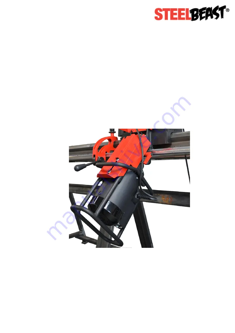
Auto Feed Bevelling Machine
for Plate Edges