The Parallel Interface
The 25-pin D-subminiature connector is used for the parallel interface.
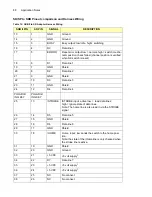
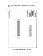
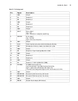
The pin assignment for the parallel interface is outlined in Figure 23 and Table 15.
Figure 23: Pin Assignment
Table 14: Pin Assignment
Pin
Signal
Description
Functionality
Pin 1
RXTX+
Transmit/receive data positive
side (B)
TXA. Differential input/output signal from the
RS485 host.
Pin 2
Shield
Signal shield
This line is connected to chassis ground at the
host end and is isolated at the slave.
The two data lines are run as a twisted pair.
The Power and Ground lines are run as
twisted pair. The shield is used to encase both
of the twisted pairs within the cable.
Pin 3
RXTX-
Transmit/receive data negative
side (A)
TXB. Complement of the differential input/out-
put from the RS485 interface.
Pin 4
Trigger
Active low trigger signal, transis-
tor-to-transistor logic (TTL), multi-
ended, pulled UP at slave with
100 K
This line is driven by the host processor (mas-
ter) to indicate to the slaves that a trigger-
based action is to be executed on the falling
edge of this signal. This action is usually pre-
conditioned by a request to the applicable
slaves.
Pin 5
Attention
Active low attention signal, open
collector, pulled UP at master
with 470 ohm
This line is driven by the SKB module (slave)
to indicate to the master that it requires the
host attention. The master is expected to poll
the slaves to determine which slave requires
attention. This signal is an open collector sig-
nal that is terminated at the host end by a 470
ohm resistor connected to Vcc.
Pin 6
V+
5 V supplies in
5 V ±5% (1 to 2.5 A maximum, configuration
dependent)
Pin 7
V+
5 V supplies in
5 V ±5% (1 to 2.5 A maximum, configuration
dependent)
Pin 8
GND
Power ground
These lines are connected to the power supply
ground, not to the chassis ground.
Pin 9
GND
Power ground
Summary of Contents for SKB Series
Page 1: ...SKB SERIES FIBEROPTIC SWITCH MODULE User Manual ...
Page 2: ...ii 10109002 Rev 001 August 2001 2001 JDS Uniphase All rights reserved ...
Page 4: ...iv ...
Page 11: ...7 Contents ...
Page 13: ...9 List of Figures ...
Page 15: ...11 List of Tables ...
Page 19: ...4 Safety Information Instructions and Symbols ...
Page 25: ...10 Introduction ...
Page 53: ...38 Operation and Control Instructions ...
Page 91: ...76 Commands ...
Page 111: ...96 Application Notes ...
Page 113: ...98 Service ...


