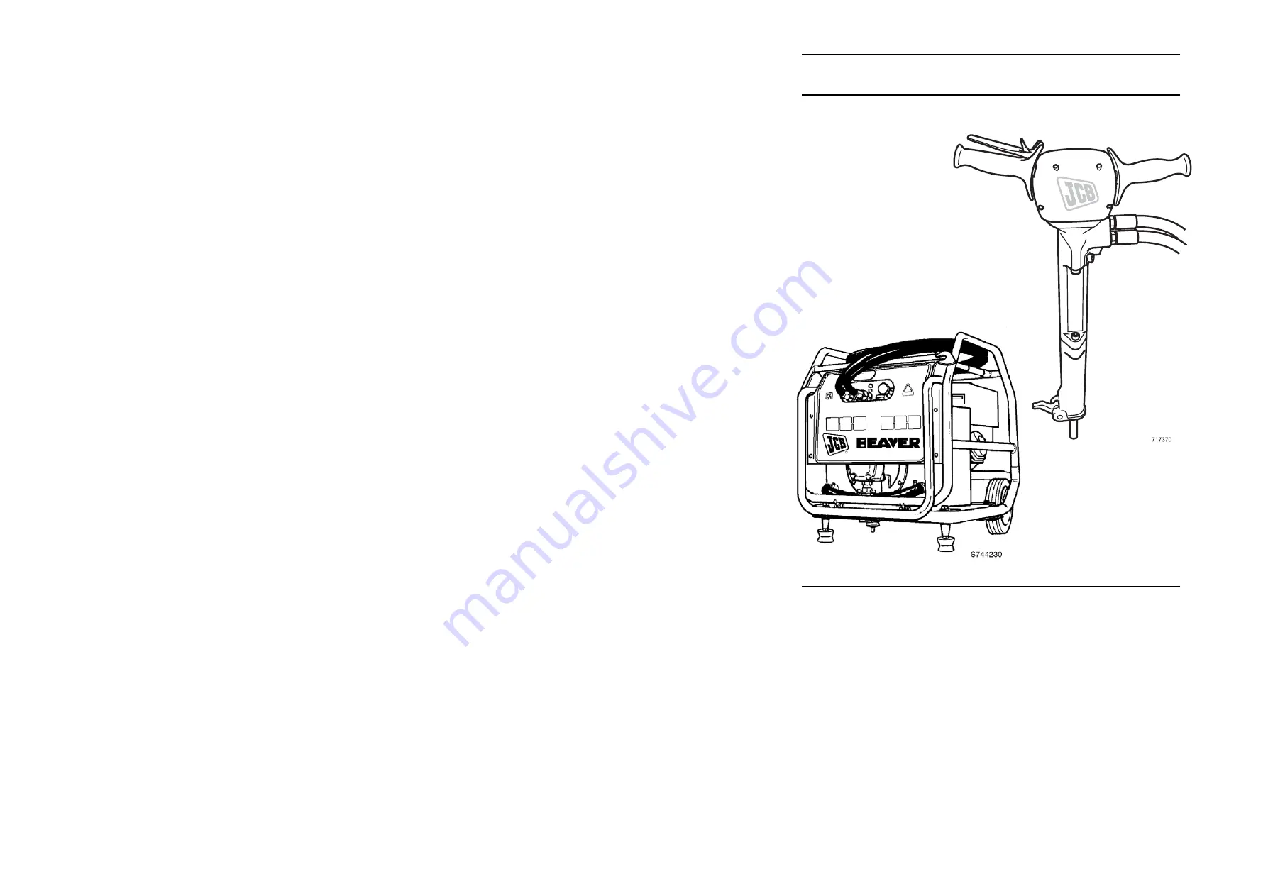
background image

JCB HAND HELD

HYDRAULIC 

EQUIPMENT

717

370

717

370

SERVICE MANUAL

9803/1250

ISSUE 2

MAY 04

PRINTED IN ENGLAND

SER

VICE

MANUAL 

:

JCB HAND HELD HYDRAULIC EQUIPMENT 

9803/1250

ISSUE 2

*9803/1250*

JCB Attachments, Riverside, Rugeley, Staffordshire WS15 2WA, England
Tel: 01889 572700

Summary of Contents for 929/92400

Page 1: ...717370 717370 SERVICE MANUAL 9803 1250 ISSUE 2 MAY 04 PRINTED IN ENGLAND SERVICE MANUAL JCB HAND HELD HYDRAULIC EQUIPMENT 9803 1250 ISSUE 2 9803 1250 JCB Attachments Riverside Rugeley Staffordshire W...

Page 2: ...WERPACKS Section E 9803 1250 Issue 2 CONTENTS WARNING Study this service manual before attempting to maintain the breaker You must understand and follow the instructions in this service manual If you...

Page 3: ...Operator s Handbook which was supplied with the breaker USING THIS MANUAL Read this manual from front to back before attempting to maintain the breaker for the first time Particular attention must be...

Page 4: ...screws Standard 20kg 23kg 26 kg 67 6 8 50 Top cover to Handle bracket capscrews Vibro 22kg 25kg 28 kg 16 1 6 11 9 Top cover to Handle bracket capscrews HM22 HM25 HM29 16 1 6 11 9 Barrel to nose capscr...

Page 5: ...d their attachment points on the breaker are as shown Each decal has a part number printed on it Use this number to order a new decal from your JCB Distributor specifying the language required In addi...

Page 6: ...ismantling HM22 25 29 B3 Breaker inspection HM22 25 29 B6 Breaker assembly HM22 25 29 B8 Charging the accumulator B11 Equipment required Charging pressure Charging procedure Fault Finding B12 Specific...

Page 7: ...nants Here are pre cautions to protect your health when handling used oil 1 Avoid prolonged excessive or repeated skin contact with used oil 2 Apply a barrier cream to the skin before handling used oi...

Page 8: ...aintenance checks must be rectified before the equipment is used Daily Clean 1 The breaker its steels and its hoses Check Breaker disconnected 2 All hydraulic connections 3 For damage to the breaker i...

Page 9: ...for oil spillage and remove the two upper barrel fixing capscrews Remove the barrel A A A 3 Before commencing dismantling clean externally Remove the hoses Remove the two lower barrel fixing capscrews...

Page 10: ...ol H from the head J 12 Remove vibration dampening springs 11 Unscrew the handle pivot pin Z nearest the trigger pin Withdraw handles assemblies from the handles control bracket Z Z Z Z G G J J H H 10...

Page 11: ...gas to escape Refit the cover screw T 15 When you are sure that all the gas in the accumulator has been evacuated remove the safety screw V from the head 16 Remove the four top cover retaining screws...

Page 12: ...D replace if necessary 3 Examine the check valve ball F and ball seats for signs of damage or excessive wear Obtain new components if necessary 4 Examine the seals for signs of wear Pay particular at...

Page 13: ...e spring ring aa with a suitable pair of pincers ee and remove The sliding bush and other components can now be removed from the nose see item 10 10 Check the spring ring aa guide rings ff 2 off carri...

Page 14: ...into the head J Fit seal on head unit J 3 Fit the trigger pin O into the handle bracket Fit the handle bracket to the head Treat the threads of the safety screw V with Loctite 270 and fit to the head...

Page 15: ...sing seal G into the head J Fit a new O ring to the housing seal G 9 Assemble the seals into the lower section of the barrel casting A Ensure seal ss has the open face uppermost seal zz is fitted in t...

Page 16: ...ead torque wrench part no 7200 01 See Torque Figures on Page A2 13 Fit 3 new seals into barrel A Insert the piston C and piston feeder D into the barrel A 14 Fasten the barrel A nose B assembly onto t...

Page 17: ...3000 lbf in2 together with female coupling JCB part no 929 06303 CHARGING PRESSURE The charging pressure should not exceed 50 bar 800 lbf in2 Refer to Specification section for specific accumulator pr...

Page 18: ...the flow rate is between 18 22 l min 3 96 4 84 gal min Note For HM29 30 litre flow rate 28 32l min 6 16 7 04 gal min Cold oil Warm up the oil supply Optimum temperature 20 70C 68 158F High return lin...

Page 19: ...B13 MAINTENANCE 9803 1250 B13 Issue 1 BREAKER HM26 NON EU...

Page 20: ...should be noted that when servicing this breaker shown on page B12 detail for the handle only reference should be made to Section C Standard handle breakers from 9803 1250 Issue 1 The remainder of the...

Page 21: ...B15 MAINTENANCE 9803 1250 B15 Issue 1 BREAKER HM22 25 29...

Page 22: ...eaker inspection Standard and Vibro damped C5 Breaker assembly Standard and Vibro damped C7 Breaker dismantling D and T picks C8 Breaker inspection D and T picks C14 Breaker D and T picks C16 Charging...

Page 23: ...icated the following instructions apply to both the standard handle and vibro handle type breakers 2 Remove the hoses Remove the two lower barrel fixing capscrews Separate the barrel A from the nose B...

Page 24: ...the head J 10 For standard handle breakers only Using a press remove roll pins N from the top cover and remove the trigger Withdraw the trigger pin O 7 Remove the seals from the lower section of the b...

Page 25: ...accumulator without first releasing the pressure can cause injury or death Gas pressure must be released before carrying out further dismantling Note Once gas has been released a special charging tool...

Page 26: ...head 21 For vibro damped handle breakers only withdraw the trigger pin O Remove the four capscrews and remove the handle bracket from the head 18 For standard handle breakers only when you are sure t...

Page 27: ...s Obtain new seals if necessary 5 For standard handle breakers only examine the rubber bushes inside the handles for signs of damage Fit new bushes if necessary These bushes are a press fit inside the...

Page 28: ...w components if necessary 9 Examine the bush inside the nose for signs of damage or wear If it is necessary to remove the bush it can be pressed out from the top of the housing using a suitable hydrau...

Page 29: ...ews Torque tighten the capscrews progressively see Introduction section ensuring theat the trigger pin remains free to move 1 Place diaphragm X into the head ensuring that the diaphragm insert is uppe...

Page 30: ...dle breaker only fit the handles to the top cover with capscrews Torque tighten the capscrews see Introduction section 7 For vibro damped handle breakers only fit the handle assembly springs Fit the h...

Page 31: ...the head assembly onto the barrel nose assembly and fit the capscrews Torque tighten the capscrews progressively see Introduction section using a Gedore narrow head torque wrench part no 7200 01 see...

Page 32: ...ie securing the hose gaiter 1 and remove the gaiter Remove the hoses 2 from the adaptors 3 Remove the adaptors and seals 4 from the accumulator assembly 4 If necessary drift out the pivot pin 7 and re...

Page 33: ...e capscrews 28 to separate the accumulator assembly from the barrel nose assembly 7 T Type only If necessary remove roll pins 18 and 19 suing a press Remove the latch 20 plunger 21 and spring 22 9 App...

Page 34: ...m the accumulator Remove the cover screw 37 to gain access to the charging screw 38 Insert a 4 mm allen key and slowly loosen the charging screw approximately 3 or 4 turns listening for all the gas to...

Page 35: ...s 48 from the lower end of the barrel 49 one each side 19 Remove seal 51 and seal housing 52 from the lower end of the barrel 49 Using a slide hammer remove seal 53 from seal housing 52 Discard the se...

Page 36: ...ck valve 43 for signs of damage or excessive wear Obtain new components if necessary 2 Examine the housing cap 29 and spool 32 for signs of damage Obtain new components if necessary 4 Examine the diap...

Page 37: ...NSPECTION D and T PICKS cont d 7 Examine slide rails 24 and springs 25 for signs of excessive wear damage or deformation Replace if necessary 8 Examine slide bearings 26 and bump stops 27 for signs of...

Page 38: ...ice Apply Loctite 242 to nose 50 and screw into the barrel using a C spanner 4 Insert piston 45 into the upper end of barrel 49 Fit new O ring 47 to piston feeder 46 and slide the piston feeder into t...

Page 39: ...de rail 24 as shown Apply light pressure to the top of the slide rail to compress the spring then swing the bottom of the slide rail over the bump stop 26 Repeat for the other side 7 Turn the accumula...

Page 40: ...ed to the top port of the accumulator head Fit the hose gaiter 1 and secure with a cable tie BREAKER ASSEMBLY D and T PICKS cont d 12 T Type only If dismantled fit the spring 22 plunger 21 and latch 2...

Page 41: ...ecification section for specific accumulator pressures CHARGING PROCEDURE Note For D and T picks access must first be gained to the accumulator assembly by carrying out Steps 1 to 8 excluding step 7 o...

Page 42: ...r lacks breaking power Insufficient available pressure Check Main Relief Valve for settings refer to Specification section Low accumulator gas pressure Re charge the accumulator as Normally associated...

Page 43: ......

Page 44: ...D SPECIFICATION 9803 1250 D Issue 1 CONTENTS JCB hydraulic breakers Standard Breakers D1 Vibro damped breakers D1 D2 D and T breakers D2 Noise and vibration data D3...

Page 45: ...Hydraulic supply relief valve setting Model Nos 929 05400 05600 76 bar min Model Nos 929 07200 08200 1100 lb in2 min All models 138 bar max 2000 lb in2 max Hydraulic return line pressure 12 bar max 1...

Page 46: ...mm 1 25 in Hydraulic supply oil type JCB Special Hydraulic Oil part no 4002 0224 EHTMA Category C or D D and T BREAKERS Breaker weight Dry with hoses D Handle 12 kg 26 4 lb T Handle 14 kg 28 6 lb Bre...

Page 47: ...7 RMS Acceleration ISO EEC LWA 8662 Part 5 m s2 929 05300 Vibro Damped 111 5 5 929 05400 Standard 111 18 9 929 05500 Vibro Damped 111 5 5 929 05600 Standard 111 18 9 929 07400 Vibro Damped 107 5 4 929...

Page 48: ...saving engine speed control a variable hydraulic flow and a unique hydraulic circuit design patent applied for which eliminates totally any possibility of pulsation damage to the oil cooler All the m...

Page 49: ...he sight level gauge 3 If necessary top up the Hydraulic Oil using the filler port Service Schedules Apart from the daily jobs the schedules are based on machine running hours Keep a regular check of...

Page 50: ...er The oil cooler fins may be cleaned using low pressure compressed air Do not attempt to clean using a wire brush as this could damage the fins Checking the Electrolyte Level WARNING Battery electrol...

Page 51: ...oil Start Model or an Electric Start Model Recoil Start Model Pull the starter grip lightly until resistance is felt then pull briskly Do not allow the starter grip to snap back against the engine Ret...

Reviews: