background image

DACS4 Operation:

User Notes:

We have made every effort to develop a software package that requires a minimum of acoustic measurement experience
and is user friendly. For best results, you should possess a basic knowledge of the Windows

3.1x operating system and

use of a pointing device (mouse or track-ball). Some knowledge of MS-DOS is also helpful, but not essential. If you do
not have any experience with the Windows operating system, please review basic program conventions in the Windows
User's Guide.

Notational Conventions:

This manual, and the online help topics found in DACS4, will use the following notational conventions:

1.  Keyboard references are noted in brackets. Here are some examples:

[Shift]

= shift key

[Ctrl] 

= control key

[F1] – [F10]

= special function keys

2.  When two or more keys are to be pressed simultaneously:

[Ctrl]+[T]

[Ctrl]+[Alt]+[Tab]

About Online Help

DACS4 has an extensive online help system. Topical information is continuously presented in a small window as you
work. The full text of each topic typically exceeds the size of the window. You can scroll through each topic using the
[PgUp] and [PgDn] keys. When you move on to the next step, the help field is automatically updated. Reading these
help topics thoroughly while working will guide you through the entire calibration process.

[F-1] Help

If the information presented online proves inadequate, more in-depth information on all topics can be found by
pressing [F1] any time during program execution. You cannot access the [F1] help topics when DACS4 is
performing a test or computing Auto-EQ.

Starting DACS4:

When you boot the DACS4 computer, it automatically begins the DACS4 program. DACS4 runs in Windows 3.1x. Prior to
starting the Windows operating system, program execution will pause, asking if there is an SDEC 1000/2500 in the sys-
tem. Press [Y]es. Next, the computer will ask you to insert the blank disk provided with the SDEC into the drive slot “A”.
Do so now and press [ENTER]. At this time, the computer will load all necessary software on the disk to create a
“LOADER” utility disk. Leave the disk in “Drive A” throughout the calibration session. For more information about the
LOADER utility, refer to the “Maintenance” section of this manual.

35

4.5

DACS4 OPERATION

Summary of Contents for SYNTHESIS SDEC-1000

Page 1: ...SYNTHESIS SDEC 1000 2500 INSTALLATION GUIDE...

Page 2: ......

Page 3: ...____________________________________20 22 Case I Replacing an analog equalizer in an existing Synthesis system _________________________20 21 Case II Installing an SDEC as part of a new Synthesis syst...

Page 4: ...ections __________________________________________________________40 4 6 DACS4 Main Screen _________________________________________________________________41 45 Response Graph _______________________...

Page 5: ...6 0 ___________________________________________INTERCONNECTION DIAGRAMS Synthesis One Interconnection Diagram _____________________________________________________58 59 Synthesis Two and Three Interc...

Page 6: ...ram_____________________________________________________41 Figure 18 DACS4 Main Calibration Screen _______________________________________________________42 Figure 19 Response Graph Window____________...

Page 7: ...instructions should be followed 5 Water and Moisture The product should not be used near water for example near a bathtub washbowl kitchen sink laundry tub in a wet base ment or near a swimming pool...

Page 8: ...n antenna discharge unit size of ground ing conductors location of antenna discharge unit connection to grounding electrodes and requirements for the grounding electrode see above figure 18 Damage Req...

Page 9: ...nto importantes que est n en los materiales de lectura que se incluyen Italiano Importanti norme di sicurezza Conservare le presenti norme per l utilizzo futuro Osservare tutte le istruzioni e le avve...

Page 10: ...eita Norsk Viktig informasjon om sikkerhet Ta vare p denne veiledningen for senere bruk F lg alle anvisningene og advarslene som er angitt p apparatet Apparatet skal alltid anvendes med korrekt spenni...

Page 11: ...ing available to correct any remaining system non linearity Fantasize about crossovers that are theoretically perfect and time domain correction delivering idealized impulse response The fun doesn t s...

Page 12: ...2 1 SDEC 1000 REAR PANEL SDEC 2500 REAR PANEL System connection after dealer installation and calibration 12 SDEC 1000 Rear Panel SDEC 2500 Rear Panel...

Page 13: ...re inordinate complexity and would result in signal quality degradation if done in the analog domain After processing high quality digital to analog converters return the signals to the analog domain...

Page 14: ...he horns tweeters and midrange drivers are mounted at somewhat different distances from the listener The SDEC can delay the sound coming from the closer drivers slightly so that all frequencies imping...

Page 15: ...s to loudspeakers and move the sweet spot to the listener This feature is called Auto time arrival correction in the Synthesis system Figure 3 Effect of Auto Time Correction Crossovers The SDEC 1000 u...

Page 16: ...cs Synthesis systems employ horn loaded drivers for cinema and direct radiators for music The SDEC contains two sets of equalization curves selected by the system controller for each of the Synthesis...

Page 17: ...equalizer Typically such devices are two edged swords able to cause at least as many problems as they solve In this case however a preprogrammed computer using proprietary algorithms developed over a...

Page 18: ...owing discussion it will be assumed that the surround processor decoder is a Synthesis SDP 2D although it may be an earlier SDP 1 or SDP 2 The SDP 1 is a Dolby Pro Logic decoder and control system whi...

Page 19: ...appropriately marked CL 3 is one example of such a rating Refer to the Synthesis S 400 S 650 Power Amplifier User s Manual for more information about selecting appropriate speaker wires AC power It is...

Page 20: ...THX wiring convention It is not used with current Synthesis surround processors On the rear panel of the SDEC are two slide switches with recessed handles Unless you are installing a CINEMA only syst...

Page 21: ...the SDEC are two slide switches with recessed handles Unless you are installing a CINEMA only system use a pencil or straightened paper clip to place both switches in the AUTO position If you are ins...

Page 22: ...emporarily The SDEC will simply pass signals through with no signal processing If the system is not performing as expected refer to Troubleshooting in Section 4 7 Power the system up for the first tim...

Page 23: ...coustics engineer using sophisticated analysis devices Using DACS4 you will be able to perform this work in a few hours time Stimulus DACS4 uses pink weighted pseudo random noise to stimulate the spea...

Page 24: ...tly what we want to do Figure 6 System Response in Five Locations Lower Trace is the Spatially Averaged Result Prior to EQ Data Post Processing A Microphone Multiplexer SMM 5 scans the microphones seq...

Page 25: ...ame arrival time At the conclusion of the calibration session all settings are transmitted to the FLASH EPROM in the SDEC and made permanent burned Target Curves Intuitive logic would tend to indicate...

Page 26: ...any carefully controlled listening tests that all three components must be timbrally neutral in order for a loudspeaker to be rated highly by listeners The design criteria therefore can be summarized...

Page 27: ...umstances If the speakers have been properly designed to begin with it matters little what the room curve looks like at high frequencies Synthesis speakers are properly designed In fact attempting to...

Page 28: ...Things To Consider When Selecting A Location For DACS4 The complete system calibration will take two to three hours therefore you should give the location of the test setup some thought Try to set up...

Page 29: ...thesis System components There is no power switch on the EVP When you plug the power supply into the AC supply a red LED on the rear panel will light Do not power up the computer at this time Using th...

Page 30: ...n nector pin springs These connectors are far more likely to fall out from the weight of the cable than it may appear Microphone Connection and Placement The DACS4 calibration kit includes five instru...

Page 31: ...tion is not always the front and center seat Wherever the primary position is this is where you will place microphone 1 You should place this microphone at ear level The microphones are not numbered a...

Page 32: ...uter at this time Using the same AC outlet for all devices will minimize ground circuit current which manifests itself as audible hum in the speakers and popping noises during data transmission from t...

Page 33: ...SDEC 1000 2500 in this system The computer will pause at this point waiting for your response DO NOT respond at this time 3 Select the AUX input on the surround processor If you used a different inpu...

Page 34: ...LEFT CENTER RIGHT all models Small 80Hz high pass LEFT RIGHT AMBIENTS Synthesis 1 Small dipole 80Hz high pass LEFT RIGHT AMBIENTS Synthesis 2 and 3 Small dipole 100Hz high pass BASS SPLIT 80Hz REARS N...

Page 35: ...ally exceeds the size of the window You can scroll through each topic using the PgUp and PgDn keys When you move on to the next step the help field is automatically updated Reading these help topics t...

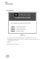
Page 36: ...y the DACS4 System You have three possible courses of action 1 Run DACS2 This is the previous release of DACS which is still suitable for calibrating any Synthesis System that uses analog equalizers a...

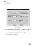
Page 37: ...enter the customer s name exactly as he or she prefers This is what will be printed on the certificate The information in section two is used to initialize the DACS4 program Use care when selecting in...

Page 38: ...actually seven possible permutations currently available each of which requires a different calibration strategy Select a Surround Processor Figure 14 Select a Surround Processor Currently there is on...

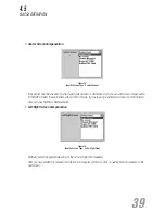
Page 39: ...e screen Cloth or None If you are using a perforated screen or cloth not listed here call your Synthesis Representative Left Right Screen Compensation Figure 16 Identify Screen Type Left Right Front S...

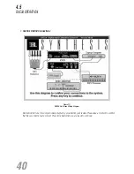
Page 40: ...ACS4 On Screen Wiring Diagram Before DACS4 runs this simple hookup diagram is provided for your review Please take a moment to confirm that these connections are correct Press Any Key when you are rea...

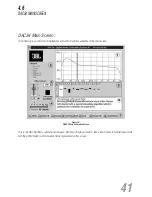
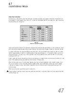
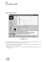
Page 41: ...vailable on the main screen Figure 18 DACS4 Main Calibration Screen This is the main Synthesis calibration workspace Before you begin calibration take a few minutes to familiarize yourself with the ei...

Page 42: ...ayed simultaneously Filters at a Glance Figure 20 Filter Setting and Control Field The settings of all filters can be reviewed here Each filter s center frequency is indicated in the small box above e...

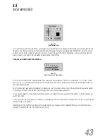
Page 43: ...r L C R left center and right AL AR ambient left and right The currently active channel is indicated by a black dot in the diamond above each channel designator Any channels that have been completed a...

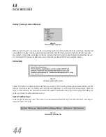
Page 44: ...in each available channel Online Help Figure 24 Continuously Updated Online Help Topical information is continuously presented here as you work The full text of each topic typically exceeds the size o...

Page 45: ...ssing F3 transmits the final settings to the SDEC and puts a check mark in the channel status indicator F4 TEST Runs a test of the currently active channel F6 EXIT Program Quit F7 Room EQ Inserts a sp...

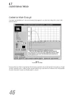
Page 46: ...7 Fresh Install First Screen Now would be a good time to begin reading the information presented in the online help field It will guide you through the entire calibration process When you have finishe...

Page 47: ...6 Typically if there is an error it will be quite large so it is easy to spot As an example If all of the speakers are about 200 from MIC 1 one channel might report 360 or 0 If one or more channels ar...

Page 48: ...possible over the target curve This is necessary for two reasons 1 The Industry standard reference level is 85dBC when the source DVD or LaserDisk is at 0dB Setting this test to fit the target will br...

Page 49: ...much the level needs to be shifted DACS4 has a special display smoothing algorithm designed to make it easy to determine the correct level You invoke the smoothed display by pressing the Shift F4 keys...

Page 50: ...dy to initiate the Auto EQ routine Press F2 now Figure 32 Results of Auto EQ Figure 32 illustrates the results of Auto EQ Notice the remaining small peaks and dips at the top of the graph With 10 band...

Page 51: ...uency Table 1 demonstrates that it is most important to fit the test over the target as well as possible from 4 to 8kHz The frequencies above and below are less critical but cannot be ignored Every ro...

Page 52: ...cting with the room Attempts to EQ the high frequencies only degrades system performance Figure 34 Auto EQ F3 Accepts settings Left and Right Ambient Calibration The calibration procedure for the ambi...

Page 53: ...ing a Cinema only system accepting the last channel signals the end of the calibration sequence Skip forward to the topic Quitting DACS4 on page 54 If you are calibrating a Cinema Music system read on...

Page 54: ...Utility When you began the SDEC calibration process DACS4 asked you to install the 3 5 floppy disk provided with the SDEC After calibration is complete this disk will contain a file that contains all...

Page 55: ...ey will not be fully effective in some instances equipment can be damaged they may actually be illegal and in many cases are downright dangerous What You Can Do During Installation First do not isolat...

Page 56: ...the particular installation you must reduce all ground path resistance to as close to 0W as possible This is the correct method of eliminating hum Do not try to break the ground by defeating the groun...

Page 57: ...50 ohms Crossover 4th order Linkwitz Reilly N A Filter Characteristics Attenuation Range 6db 12dB 6db 12dB Center Frequency Range 20Hz 20kHz 20Hz 20kHz Bandwidth 0 1 5 octaves 0 1 5 octaves Total Ban...

Page 58: ...SYNTHESIS ONE Interconnection Diagram S400 S400 S650 S650 SDP 2D SDEC 1000 SDP RFD 58 59 6 0 INTERCONNECTION DIAGRAMS...

Page 59: ...SYNTHESIS TWO THREE Interconnection Diagram S650 SDP 2D SDEC 2500 S400 SDP RFD 60 61 6 0 INTERCONNECTION DIAGRAMS...

Page 60: ...SYNTHESIS ONE Control Wiring Diagram SDP 2D SDEC 1000 S400 S400 S650 S650 SDP RFD 62 63 7 0 CONTROL WIRING DIAGRAMS...

Page 61: ...SYNTHESIS TWO THREE Control Wiring Diagram S650 SDP 2D SDEC 2500 S400 SDP RFD 64 65 7 0 CONTROL WIRING DIAGRAMS...

Reviews: